 半导体工艺实验报告 交大.docx
- 文档编号:9576754
- 上传时间:2023-02-05
- 格式:DOCX
- 页数:83
- 大小:969.23KB
半导体工艺实验报告 交大.docx
《半导体工艺实验报告 交大.docx》由会员分享,可在线阅读,更多相关《半导体工艺实验报告 交大.docx(83页珍藏版)》请在冰豆网上搜索。

半导体工艺实验报告交大
半导体制造工艺实验
姓名:
章叶满班级:
电子1001学号:
******21
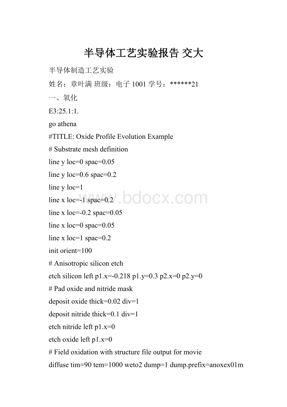
一、氧化
E3:
25.1:
1.
goathena
#TITLE:
OxideProfileEvolutionExample
#Substratemeshdefinition
lineyloc=0spac=0.05
lineyloc=0.6spac=0.2
lineyloc=1
linexloc=-1spac=0.2
linexloc=-0.2spac=0.05
linexloc=0spac=0.05
linexloc=1spac=0.2
initorient=100
#Anisotropicsiliconetch
etchsiliconleftp1.x=-0.218p1.y=0.3p2.x=0p2.y=0
#Padoxideandnitridemask
depositoxidethick=0.02div=1
depositnitridethick=0.1div=1
etchnitrideleftp1.x=0
etchoxideleftp1.x=0
#Fieldoxidationwithstructurefileoutputformovie
diffusetim=90tem=1000weto2dump=1dump.prefix=anoxex01m
tonyplot-stanoxex01m*.str
structureoutfile=anoxex01_0.str
quit
实验截图:
实验分析:
当氧扩散穿越已生长的氧化剂时,它是在各个方向上扩散的。
一些氧原子纵向扩散进入硅,另一些氧原子横向扩散。
这意味着在氮化硅掩膜下有着轻微的侧面氧化生长。
由于氧化层比消耗的硅更厚,所以在氮化物掩膜下的氧化生长将抬高氮化物的边缘。
这就是LOCOS氧化工艺中的“鸟嘴效应”。
这种现象是LOCOS氧化工艺中不受欢迎的副产物。
氧化物较厚时,“鸟嘴效应”更显著。
为了减小氮化物掩膜和硅之间的应力,在它们之间热生长一层薄氧化层—垫氧。
或者可以使用浅槽隔离技术来代替LOCOS,这样就可以避免“鸟嘴效应”。
E3:
25.1:
2.
goathena
#TITLE:
MixedAmbientOxidationExample
#Thisexampledemonstratesmixedambientoxidationin1D
#
foreachgas(2.to8.step2.)
#
linexloc=0.0sp=1.0
linexloc=1.0sp=1.0
lineyloc=0.0sp=0.05
lineyloc=1.0sp=0.05
initialize
#
diffusetime=60temperature=1000f.o2=gasf.h2=20.
structureoutfile=anoxex02_gas.str
#
end
tonyplot-stanoxex02*.str
quit
实验截图:
实验分析:
实验描述的是当气流中通过四种不同浓度比的由氧气、水、氢、氮构成的混合气体时Si氧化成SiO2的不同程度,其中参数F.O2,F.H2O,F.H2,F.N2是每个气流中流的氧气、水、氢、氮的扩散语句。
由图可以看出,不同的气体比例会得到不同的氧化效果。
潮湿的氧化环境水蒸气在二氧化硅中扩散的更快、溶解度更高,更有利于硅氧化生长速率的加快。
而无论是何种程度的氧化,二氧化硅的生长都是要消耗硅的,氧化生长的越多,硅消耗的越多。
硅消耗的厚度占氧化物总厚度的0.46。
氧化物生长发生在氧分子通过已生成的二氧化硅层运动进入硅片的过程中。
E3:
25.1:
9.goathena
#TITLE:
OrientationdependentOxidationExample
lineyloc=0spac=0.1
lineyloc=4spac=0.1
linexloc=-1spac=0.1
linexloc=1spac=0.1
#
#initializewithorientationofsidewallsalong100direction
initorient=100rot.sub=0
methodgridinit.ox=0.02grid.ox=0.02
#Anisotropicsiliconetch
etchsiliconrightp1.x=0.0p1.y=2.0p2.x=0.0p2.y=0.0
#Fieldoxidation
diffusetime=20tem=1000wet
#
#
extractname="toxx"thicknessoxidemat.occno=1x.val=0.50
extractname="toxy"thicknessoxidemat.occno=1y.val=1.05
#Savethestructure
structureoutfile=anoxex09_1.str
lineyloc=0spac=0.1
lineyloc=4spac=0.1
linexloc=-1spac=0.1
linexloc=1spac=0.1
#
#initializewithorientationofsidewallsalong110direction
initorient=100rot.sub=45
#Anisotropicsiliconetch
etchsiliconrightp1.x=0.0p1.y=2.0p2.x=0.0p2.y=0.0
#Fieldoxidation
diffusetime=20tem=1000wet
extractname="toxx"thicknessoxidemat.occno=1x.val=0.50
extractname="toxy"thicknessoxidemat.occno=1y.val=1.05
#Savethestructure
structureoutfile=anoxex09_2.str
#
#ploteachofthesavedstructures
tonyplot-overlayanoxex09_1.stranoxex09_2.str-setanoxex09.set
实验截图:
实验分析:
上图中红线代表忽略晶向影响的情况,绿线代表考虑晶向影响的情况。
实验表明,在氧化生长的线性阶段侧墙的生长氧化受到硅晶向的影响。
而在抛物线阶段侧墙的生长氧化几乎不受硅晶向的影响。
E3:
25.1:
10.goathena
#simflags="-V5.6.0.R"
#TITLE:
OxidationOverlapinNarrowTrenchExample
#
#Thisexamplesimulatesoxidationinanarrowtrench
#
linexloc=0.0spac=0.2
linexloc=1.0spac=0.05
#
lineyloc=0.0spac=0.05
lineyloc=0.7spac=0.25
lineyloc=1.4spac=0.05
lineyloc=2spac=0.25
initialize
#
etchsiliconstartx=0.95y=0.0
etchcontinuex=1.0y=0.0
etchcontinuex=1.0y=1.5
etchdonex=0.8y=1.5
#
structuremirrorright
#
#Specifyingfillonmethodstatementcausesvoidsinoxidetobefilled
methodcompressfermi
diffusetime=8temp=1150wetdump=1dump.prefix=anoxex10m
structureoutfile=anoxex10.str
#
tonyplot-stanoxex10m*.stranoxex10.str
quit
实验截图:
实验分析:
上图演示的是沟槽夹断现象。
在用PECVD进行淀积的时候,随着淀积过程的不断进行,膜在间隙入口出产生夹断现象,并且导致在间隙填充中的空洞,影响电学特性和长期可靠性。
为了避免这一现象的产生,我们可以采用HDPCVD进行淀积。
HDPCVD即高密度等离子体CVD,它的主要优点在于可以在300到400摄氏度较低的淀积温度下,制备出能够填充高深宽比间隙的膜。
二、扩散
24.1:
1.goathena
#TITLE:
SimpleBoronAnneal
#thexdimensiondefinition
linexloc=0.0spacing=0.1
linexloc=0.1spacing=0.1
#theverticaldefinition
lineyloc=0spacing=0.02
lineyloc=2.0spacing=0.20
#initializethemesh
initsiliconc.phos=1.0e14
#performuniformboronimplant
implantborondose=1e13energy=70
#performdiffusion
diffusetime=30temperature=1000
#
extractname="xj"xjsiliconmat.occno=1x.val=0.0junc.occno=1
#savethestructure
structureoutfile=andfex01.str
#plotthefinalprofile
tonyplotandfex01.str
quit
实验截图:
实验分析:
上图实验为硼的注入和退火的过程。
红、绿、蓝线分别表示硼、磷以及净掺杂。
注入后形成高斯分布。
随着硼浓度的下降,净掺杂浓度等于磷的浓度。
离子注入通过高压离子轰击把杂质引入硅片,杂质通过与硅片发生原子级的高能碰撞,才能被注入。
离子注入会将原子撞击出晶格结构而损伤硅片晶格。
退火能够加热被注入硅片,修复晶格缺陷,还能使杂质原子移动到晶格点,将其激活,最小化杂质扩散。
24.1:
2.
goathena
#OEDofBoron
#thexdimensiondefinition
linexloc=0.0spacing=0.1
linexloc=0.1spacing=0.1
#theverticaldefinition
lineyloc=0spacing=0.02
lineyloc=2.0spacing=0.20
lineyloc=25.0spacing=2.5
#initializethemesh
initsiliconc.phos=1.0e14
#performuniformboronimplant
implantborondose=1e13energy=70
#setdiffusionmodelforOED
methodtwo.dim
#performdiffusion
diffusetime=30temperature=1000dryo2
#
extractname="xj_two.dim"xjsiliconmat.occno=1x.val=0.0junc.occno=1
#savethestructure
structureoutfile=andfex02_0.str
#repeatthesimulationwithdefaultFERMImodel
goathena
#TITLE:
SimpleBoronAnneal
#thexdimensiondefinition
linexloc=0.0spacing=0.1
linexloc=0.1spacing=0.1
#theverticaldefinition
lineyloc=0spacing=0.02
lineyloc=2.0spacing=0.20
lineyloc=25.0spacing=2.5
#initializethemesh
initsiliconc.phos=1.0e14
#performuniformboronimplant
implantborondose=1e13energy=70
#selectdiffusionmodel
methodfermi
#performdiffusion
diffusetime=30temperature=1000dryo2
#
extractname="xj_fermi"xjsiliconmat.occno=1x.val=0.0junc.occno=1
#savethestructure
structureoutfile=andfex02_1.str
#comparediffusionmodels
tonyplot-overlayandfex02_0.strandfex02_1.str-setandfex02.set
实验截图:
实验分析:
扩散工艺有二步,第一步为恒定表面浓度的扩散,第二步为有限源的扩散。
在杂质浓度很高时,扩散系数不再是常数,而与掺杂浓度相关。
该实验演示了氧化增强扩散(OED)的模型。
对硼来说,其在硅中的扩散可以通过间隙硅原子进行。
氧化时由于体积膨胀,造成大量硅间隙原子注入,增加了硼的扩散系数。
有利于扩散的进行。
24.1:
3.
goathena
#thexdimensiondefinition
linexloc=0.0spacing=0.1
linexloc=0.1spacing=0.1
#theverticaldefinition
lineyloc=0spacing=0.005
lineyloc=2.0spacing=0.20
lineyloc=25.0spacing=2.5
#initializethemesh
initsiliconc.boron=1.0e17
#depositscreenoxide
depositoxidethickness=0.005div=2
#performarsenicimplantwithdamage
implantarsenicdose=1.0e15energy=40tilt=7unit.damagedam.factor=0.1
#setdiffusionmodelforTED
methodfull.cpl
#performdiffusion
diffusetime=15/60temperature=1000
#
extractname="xj_fullcpl"xjsiliconmat.occno=1x.val=0.0junc.occno=1
#savethestructure
structureoutfile=andfex03_0.str
#repeatthesimulationwithFERMImodel
#thexdimensiondefinition
linexloc=0.0spacing=0.1
linexloc=0.1spacing=0.1
#theverticaldefinition
lineyloc=0spacing=0.005
lineyloc=2.0spacing=0.20
lineyloc=25.0spacing=2.5
#initializethemesh
initsiliconc.boron=1.0e17
#depositscreenoxide
depositoxidethickness=0.005div=2
#performarsenicimplantwithdamage
implantarsenicdose=1.0e15energy=40tilt=7unit.damagedam.factor=0.1
#setdefaultmodel
methodfermi
#performdiffusion
diffusetime=15/60temperature=1000
#
extractname="xj_fermi"xjsiliconmat.occno=1x.val=0.0junc.occno=1
#savethestructure
structureoutfile=andfex03_1.str
#comparediffusionmodels
tonyplot-overlayandfex03_0.strandfex03_1.str-setandfex03.set
实验截图:
实验分析:
杂质在硅原子间穿行,会在晶格中产生一条受损伤的路径,损伤的情况决定于杂质离子的轻重。
上图为重离子注入造成晶格损伤,重离子每次与硅原子碰撞都会转移许多能量,并沿相对较小的散射角度偏转。
每个位移硅原子也会产生大量的位移。
重离子注入造成的晶格损伤需要进行RTA来进行修复晶格损伤。
使扩散效应增强。
另外,还能使杂质原子移动到晶格点,将其激活。
24.1:
7.
goathena
#TITLE:
Emitterpusheffectexample
#
linexloc=0.0spac=0.2
linexloc=2.5spac=0.8
linexloc=3.0spac=0.2
#
lineyloc=0.00spac=0.04
lineyloc=0.3spac=0.06
lineyloc=2.0spac=0.8
lineyloc=10.0spac=2.0
#
initc.phos=1e15
#
implantborondose=1e13energy=40
#
depositnitridethick=.2div=4
#
etchrightnitridep1.x=2.5
relaxy.min=1.5
#
implantphosphordose=1e16energy=30
#
etchnitrideall
#
methodcompressfull.cpl
diffusetime=30temp=1000
#
structureoutfile=andfex07.str
#
tonyplot-standfex07.str-setandfex07.set
quit
实验截图:
实验分析:
本实验演示的是硼掺杂发射极的推进效应。
在磷发射区下的硼比旁边的硼扩散得快,导致基区宽度改变。
硼扩散增强是由于磷与空位相互作用形成的PV对分解所带来的复合效应。
硼附近PV对的分解会增加空位的浓度,加快了硼扩散的速度。
三、离子注入
23.1:
1.
goathena
#TITLE:
ComparisonofGauss,PearsonandSVDPmethod
linexloc=0.0spacing=0.25
linexloc=0.25spacing=0.25
lineyloc=0spacing=0.01
lineyloc=0.50spacing=0.01
#initializethemesh
initsilicon
#Gauss(symmetrical)implant(parametersareinstd_tables)
momentsstd_tables
implantphosdose=1e14energy=40gauss
structoutf=aniiex01_0.str
linexloc=0.0spacing=0.25
linexloc=0.25spacing=0.25
lineyloc=0spacing=0.01
lineyloc=0.50spacing=0.01
#initializethemesh
initsilicon
#UsesinglePearson(parametersareinstd_tables)
momentsstd_tables
implantphosdose=1e14energy=40pearsonprint.mom
structoutf=aniiex01_1.str
linexloc=0.0spacing=0.25
linexloc=0.25spacing=0.25
lineyloc=0spacing=0.01
lineyloc=0.50spacing=0.01
#initializethemesh
initsilicon
#UseSVDPmethod(default)
momentssvdp_tables
implantphosdose=1e14energy=40print.mom
structoutf=aniiex01_2.str
tonyplot-overlayaniiex01_*.str-setaniiex01.set
quit
实验截图:
实验分析:
离子注入是离子化后的原子在强电场的加速作用下,注射进入靶材料的表层,以改变这种材料表层的物理或化学性质的一个工艺工程。
本实验对离子注入模型——高斯模型、皮尔逊模型以及双皮尔森模型三种模型进行了比较分析。
显上图中是扩散杂质随厚度增加的三种分布情况。
其中,双皮尔森模型的浓度分布曲线和另外两种有很大差异。
23.1:
2.
goathena
#TiltangledependenceusingSVDPmodel
linexloc=0.0spac=0.1
linexloc=1.0spac=0.1
lineyloc=0sp
- 配套讲稿:
如PPT文件的首页显示word图标,表示该PPT已包含配套word讲稿。双击word图标可打开word文档。
- 特殊限制:
部分文档作品中含有的国旗、国徽等图片,仅作为作品整体效果示例展示,禁止商用。设计者仅对作品中独创性部分享有著作权。
- 关 键 词:
- 半导体工艺实验报告 交大 半导体 工艺 实验 报告
 冰豆网所有资源均是用户自行上传分享,仅供网友学习交流,未经上传用户书面授权,请勿作他用。


 《城市规划基本知识》深刻复习要点.docx
