 通信原理基于matlab的计算机仿真.docx
- 文档编号:8247014
- 上传时间:2023-01-30
- 格式:DOCX
- 页数:47
- 大小:28.52KB
通信原理基于matlab的计算机仿真.docx
《通信原理基于matlab的计算机仿真.docx》由会员分享,可在线阅读,更多相关《通信原理基于matlab的计算机仿真.docx(47页珍藏版)》请在冰豆网上搜索。

通信原理基于matlab的计算机仿真
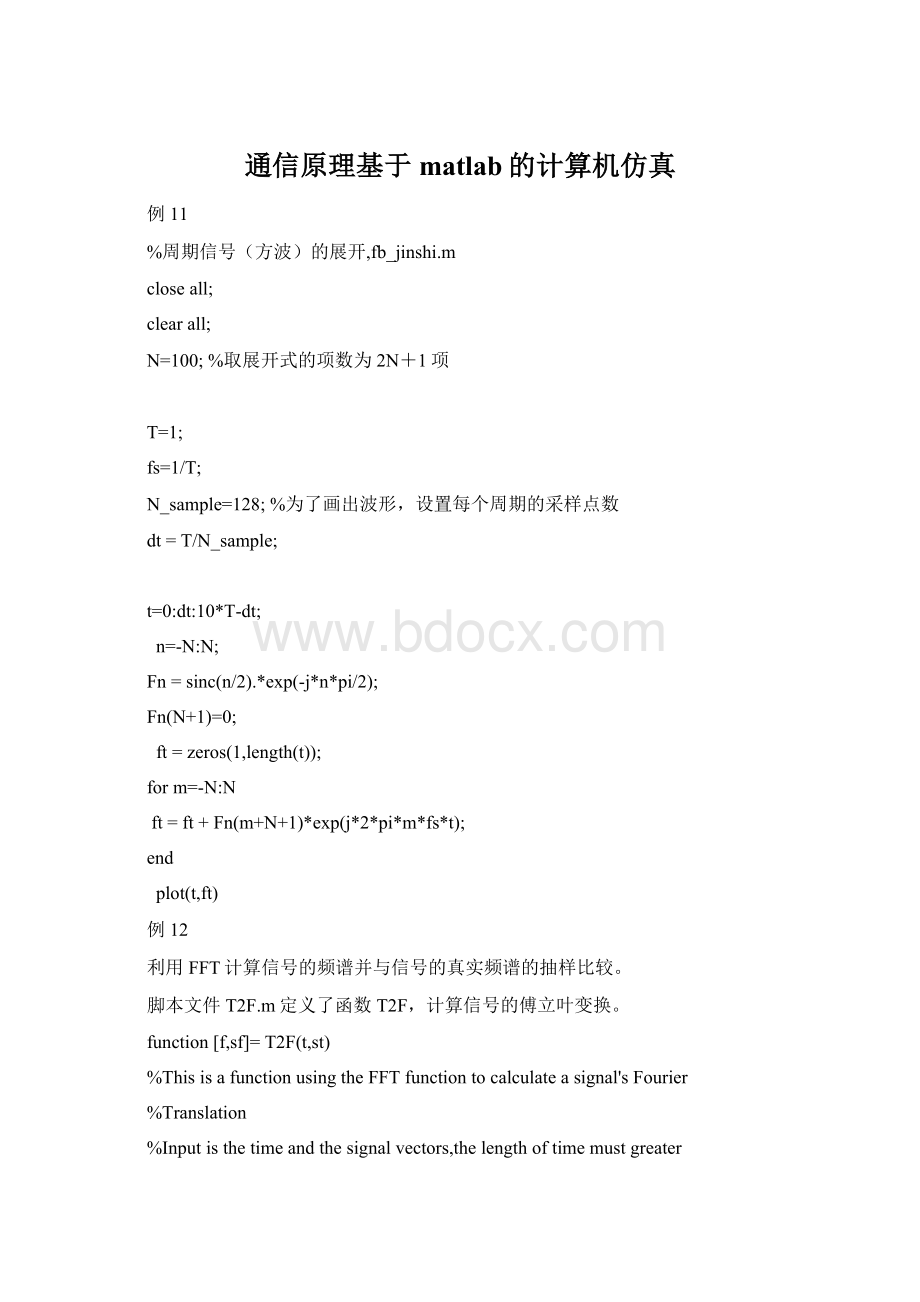
例11
%周期信号(方波)的展开,fb_jinshi.m
closeall;
clearall;
N=100;%取展开式的项数为2N+1项
T=1;
fs=1/T;
N_sample=128;%为了画出波形,设置每个周期的采样点数
dt=T/N_sample;
t=0:
dt:
10*T-dt;
n=-N:
N;
Fn=sinc(n/2).*exp(-j*n*pi/2);
Fn(N+1)=0;
ft=zeros(1,length(t));
form=-N:
N
ft=ft+Fn(m+N+1)*exp(j*2*pi*m*fs*t);
end
plot(t,ft)
例12
利用FFT计算信号的频谱并与信号的真实频谱的抽样比较。
脚本文件T2F.m定义了函数T2F,计算信号的傅立叶变换。
function[f,sf]=T2F(t,st)
%ThisisafunctionusingtheFFTfunctiontocalculateasignal'sFourier
%Translation
%Inputisthetimeandthesignalvectors,thelengthoftimemustgreater
%than2
%Outputisthefrequencyandthesignalspectrum
dt=t
(2)-t
(1);
T=t(end);
df=1/T;
N=length(st);
f=-N/2*df:
df:
N/2*df-df;
sf=fft(st);
sf=T/N*fftshift(sf);
脚本文件F2T.m定义了函数F2T,计算信号的反傅立叶变换。
function[tst]=F2T(f,sf)
%Thisfunctioncalculatethetimesignalusingifftfunctionfortheinput
%signal'sspectrum
df=f
(2)-f
(1);
Fmx=(f(end)-f
(1)+df);
dt=1/Fmx;
N=length(sf);
T=dt*N;
%t=-T/2:
dt:
T/2-dt;
t=0:
dt:
T-dt;
sff=fftshift(sf);
st=Fmx*ifft(sff);
另写脚本文件fb_spec.m如下:
%方波的傅氏变换,fb_spec.m
clearall;closeall;
T=1;
N_sample=128;
dt=T/N_sample;
t=0:
dt:
T-dt;
st=[ones(1,N_sample/2),-ones(1,N_sample/2)];%方波一个周期
subplot(211);
plot(t,st);
axis([01-22]);
xlabel('t');ylabel('s(t)');
subplot(212);
[fsf]=T2F(t,st);%方波频谱
plot(f,abs(sf));holdon;
axis([-101001]);
xlabel('f');ylabel('|S(f)|');
%根据傅氏变换计算得到的信号频谱相应位置的抽样值
sff=T^2*j*pi*f*0.5.*exp(-j*2*pi*f*T).*sinc(f*T*0.5).*sinc(f*T*0.5);
plot(f,abs(sff),'r-')
例13
%信号的能量计算或功率计算,sig_pow.m
clearall;
closeall;
dt=0.01;
t=0:
dt:
5;
s1=exp(-5*t).*cos(20*pi*t);
s2=cos(20*pi*t);
E1=sum(s1.*s1)*dt;%s1(t)的信号能量
P2=sum(s2.*s2)*dt/(length(t)*dt);%s2(t)的信号功率s
[f1s1f]=T2F(t,s1);
[f2s2f]=T2F(t,s2);
df=f1
(2)-f1
(1);
E1_f=sum(abs(s1f).^2)*df;%s1(t)的能量,用频域方式计算
df=f2
(2)-f2
(1);
T=t(end);
P2_f=sum(abs(s2f).^2)*df/T;%s2(t)的功率,用频域方式计算
figure
(1)
subplot(211)
plot(t,s1);
xlabel('t');ylabel('s1(t)');
subplot(212)
plot(t,s2)
xlabel('t');ylabel('s2(t)');
例14
%方波的傅氏变换,sig_band.m
clearall;
closeall;
T=1;
N_sample=128;
dt=1/N_sample;
t=0:
dt:
T-dt;
st=[ones(1,N_sample/2)-ones(1,N_sample/2)];
df=0.1/T;
Fx=1/dt;
f=-Fx:
df:
Fx-df;
%根据傅氏变换计算得到的信号频谱
sff=T^2*j*pi*f*0.5.*exp(-j*2*pi*f*T).*sinc(f*T*0.5).*sinc(f*T*0.5);
plot(f,abs(sff),'r-')
axis([-101001]);
holdon;
sf_max=max(abs(sff));
line([f
(1)f(end)],[sf_maxsf_max]);
line([f
(1)f(end)],[sf_max/sqrt
(2)sf_max/sqrt
(2)]);%交点处为信号功率下降3dB处
Bw_eq=sum(abs(sff).^2)*df/T/sf_max.^2;%信号的等效带宽
例15
%带通信号经过带通系统的等效基带表示,sig_bandpass.m
clearall;
closeall;
dt=0.01;
t=0:
dt:
5;
s1=exp(-t).*cos(20*pi*t);%输入信号
[f1s1f]=T2F(t,s1);%输入信号的频谱
s1_lowpass=hilbert(s1).*exp(-j*2*pi*10*t);%输入信号的等效基带信号
[f2s2f]=T2F(t,s1_lowpass);%输入等效基带信号的频谱
h2f=zeros(1,length(s2f));
[ab]=find(abs(s1f)==max(abs(s1f)));%找到带通信号的中心频率
h2f(201-25:
201+25)=1;
h2f(301-25:
301+25)=1;
h2f=h2f.*exp(-j*2*pi*f2);%加入线性相位,
[t1h1]=F2T(f2,h2f);%带通系统的冲激响应
h1_lowpass=hilbert(h1).*exp(-j*2*pi*10*t1);%等效基带系统的冲激响应
figure
(1)
subplot(521);
plot(t,s1);
xlabel('t');ylabel('s1(t)');title('带通信号');
subplot(523);
plot(f1,abs(s1f));
xlabel('f');ylabel('|S1(f)|');title('带通信号幅度谱');
subplot(522)
plot(t,real(s1_lowpass));
xlabel('t');ylabel('Re[s_l(t)]');title('等效基带信号的实部');
subplot(524)
plot(f2,abs(s2f));
xlabel('f');ylabel('|S_l(f)|');title('等效基带信号的幅度谱');
%画带通系统及其等效基带的图
subplot(525)
plot(f2,abs(h2f));
xlabel('f');ylabel('|H(f)|');title('带通系统的传输响应幅度谱');
subplot(527)
plot(t1,h1);
xlabel('t');ylabel('h(t)');title('带通系统的冲激响应');
subplot(526)
[f3hlf]=T2F(t1,h1_lowpass);
plot(f3,abs(hlf));
xlabel('f');ylabel('|H_l(f)|');title('带通系统的等效基带幅度谱');
subplot(528)
plot(t1,h1_lowpass);
xlabel('t');ylabel('h_l(t)');title('带通系统的等效基带冲激响应');
%画出带通信号经过带通系统的响应及等效基带信号经过等效基带系统的响应
tt=0:
dt:
t1(end)+t(end);
yt=conv(s1,h1);
subplot(529)
plot(tt,yt);
xlabel('t');ylabel('y(t)');title('带通信号与带通系统响应的卷积')
ytl=conv(s1_lowpass,h1_lowpass).*exp(j*2*pi*10*tt);
subplot(5,2,10)
plot(tt,real(yt));
xlabel('t');ylabel('y_l(t)cos(20*pi*t');
title('等效基带与等效基带系统响应的卷积×中心频率载波')
例1-6
%例:
窄带高斯过程,文件zdpw.m
clearall;closeall;
N0=1;%双边功率谱密度
fc=10;%中心频率
B=1;%带宽
dt=0.01;
T=100;
t=0:
dt:
T-dt;
%产生功率为N0*B的高斯白噪声
P=N0*B;
st=sqrt(P)*randn(1,length(t));
%将上述白噪声经过窄带带通系统,
[f,sf]=T2F(t,st);%高斯信号频谱
figure
(1)
plot(f,abs(sf));%高斯信号的幅频特性
[ttgt]=bpf(f,sf,fc-B/2,fc+B/2);%高斯信号经过带通系统
glt=hilbert(real(gt));%窄带信号的解析信号,调用hilbert函数得到解析信号
glt=glt.*exp(-j*2*pi*fc*tt);
[ff,glf]=T2F(tt,glt);
figure
(2)
plot(ff,abs(glf));
xlabel('频率(Hz)');ylabel('窄带高斯过程样本的幅频特性')
figure(3)
subplot(411);
plot(tt,real(gt));
title('窄带高斯过程样本')
subplot(412)
plot(tt,real(glt).*cos(2*pi*fc*tt)-imag(glt).*sin(2*pi*fc*tt))
title('由等效基带重构的窄带高斯过程样本')
subplot(413)
plot(tt,real(glt));
title('窄带高斯过程样本的同相分量')
subplot(414)
plot(tt,imag(glt));
xlabel('时间t(秒)');title('窄带高斯过程样本的正交分量')
%求窄带高斯信号功率;注:
由于样本的功率近似等于随机过程的功率,因此可能出现一些偏差
P_gt=sum(real(gt).^2)/T;
P_glt_real=sum(real(glt).^2)/T;
P_glt_imag=sum(imag(glt).^2)/T;
%验证窄带高斯过程的同相分量、正交分量的正交性
a=real(glt)*(imag(glt))'/T;
用到的子函数
function[t,st]=bpf(f,sf,B1,B2)
%Thisfunctionfilteraninputatfrequencydomainbyanidealbandpassfilter
%Inputs:
%f:
frequencysamples
%sf:
inputdataspectrumsamples
%B1:
bandpass'slowerfrequency
%B2:
bandpass'shigherfrequency
%Outputs:
%t:
frequencysamples
%st:
outputdata'stimesamples
df=f
(2)-f
(1);
T=1/df;
hf=zeros(1,length(f));
bf=[floor(B1/df):
floor(B2/df)];
bf1=floor(length(f)/2)+bf;
bf2=floor(length(f)/2)-bf;
hf(bf1)=1/sqrt(2*(B2-B1));
hf(bf2)=1/sqrt(2*(B2-B1));
yf=hf.*sf.*exp(-j*2*pi*f*0.1*T);
[t,st]=F2T(f,yf);
例1-7
%显示模拟调制的波形及解调方法DSB,文件mdsb.m
%信源
closeall;
clearall;
dt=0.001;%时间采样间隔
fm=1;%信源最高频率
fc=10;%载波中心频率
T=5;%信号时长
t=0:
dt:
T;
mt=sqrt
(2)*cos(2*pi*fm*t);%信源
%N0=0.01;%白噪单边功率谱密度
%DSBmodulation
s_dsb=mt.*cos(2*pi*fc*t);
B=2*fm;
%noise=noise_nb(fc,B,N0,t);
%s_dsb=s_dsb+noise;
figure
(1)
subplot(311)
plot(t,s_dsb);holdon;%画出DSB信号波形
plot(t,mt,'r--');%标示mt的波形
title('DSB调制信号');
xlabel('t');
%DSBdemodulation
rt=s_dsb.*cos(2*pi*fc*t);
rt=rt-mean(rt);
[f,rf]=T2F(t,rt);
[t,rt]=lpf(f,rf,2*fm);
subplot(312)
plot(t,rt);holdon;
plot(t,mt/2,'r--');
title('相干解调后的信号波形与输入信号的比较');
xlabel('t')
subplot(313)
[f,sf]=T2F(t,s_dsb);
psf=(abs(sf).^2)/T;
plot(f,psf);
axis([-2*fc2*fc0max(psf)]);
title('DSB信号功率谱');
xlabel('f');
function[tst]=lpf(f,sf,B)
%Thisfunctionfilteraninputdatausingalowpassfilter
%Inputs:
f:
frequencysamples
%sf:
inputdataspectrumsamples
%B:
lowpass'sbandwidthwitharectanglelowpass
%Outputs:
t:
timesamples
%st:
outputdata'stimesamples
df=f
(2)-f
(1);
T=1/df;
hf=zeros(1,length(f));
bf=[-floor(B/df):
floor(B/df)]+floor(length(f)/2);
hf(bf)=1;
yf=hf.*sf;
[t,st]=F2T(f,yf);
st=real(st);
例1-8
%显示模拟调制的波形及解调方法AM,文件mam.m
%信源
closeall;
clearall;
dt=0.001;%时间采样间隔
fm=1;%信源最高频率
fc=10;%载波中心频率
T=5;%信号时长
t=0:
dt:
T;
mt=sqrt
(2)*cos(2*pi*fm*t);%信源
%N0=0.01;%白噪单边功率谱密度
%AMmodulation
A=2;
s_am=(A+mt).*cos(2*pi*fc*t);
B=2*fm;%带通滤波器带宽
%noise=noise_nb(fc,B,N0,t);%窄带高斯噪声产生
%s_am=s_am+noise;
figure
(1)
subplot(311)
plot(t,s_am);holdon;%画出AM信号波形
plot(t,A+mt,'r--');%标示AM的包络
title('AM调制信号及其包络');
xlabel('t');
%AMdemodulation
rt=s_am.*cos(2*pi*fc*t);%相干解调
rt=rt-mean(rt);
[f,rf]=T2F(t,rt);
[t,rt]=lpf(f,rf,2*fm);%低通滤波
subplot(312)
plot(t,rt);holdon;
plot(t,mt/2,'r--');
title('相干解调后的信号波形与输入信号的比较');
xlabel('t')
subplot(313)
[f,sf]=T2F(t,s_am);
psf=(abs(sf).^2)/T;
plot(f,psf);
axis([-2*fc2*fc0max(psf)]);
title('AM信号功率谱');
xlabel('f');
例1-9
%显示模拟调制的波形及解调方法SSB,文件mssb.m
%信源
closeall;
clearall;
dt=0.001;%时间采样间隔
fm=1;%信源最高频率
fc=10;%载波中心频率
T=5;%信号时长
t=0:
dt:
T;
mt=sqrt
(2)*cos(2*pi*fm*t);%信源
%N0=0.01;%白噪单边功率谱密度
%SSBmodulation
s_ssb=real(hilbert(mt).*exp(j*2*pi*fc*t));
B=fm;
%noise=noise_nb(fc,B,N0,t);
%s_ssb=s_ssb+noise;
figure
(1)
subplot(311)
plot(t,s_ssb);holdon;%画出SSB信号波形
plot(t,mt,'r--');%标示mt的波形
title('SSB调制信号');
xlabel('t');
%SSBdemodulation
rt=s_ssb.*cos(2*pi*fc*t);
rt=rt-mean(rt);
[f,rf]=T2F(t,rt);
[t,rt]=lpf(f,rf,2*fm);
subplot(312)
plot(t,rt);holdon;
plot(t,mt/2,'r--');
title('相干解调后的信号波形与输入信号的比较');
xlabel('t')
subplot(313)
[f,sf]=T2F(t,s_ssb);
psf=(abs(sf).^2)/T;
plot(f,psf);
axis([-2*fc2*fc0max(psf)]);
title('SSB信号功率谱');
xlabel('f');
例2-0
%显示模拟调制的波形及解调方法VSB,文件mvsb.m
%信源
closeall;
clearall;
dt=0.001;%时间采样间隔
fm=5;%信源最高频率
fc=20;%载波中心频率
T=5;%信号时长
t=0:
dt:
T;
mt=sqrt
(2)*(cos(2*pi*fm*t)+sin(2*pi*0.5*fm*t));%信源
%VSBmodulation
s_vsb=mt.*cos(2*pi*fc*t);
B=1.2*fm;
[f,sf]=T2F(t,s_vsb);
[t,s_vsb]=vsbpf(f,sf,0.2*fm,1.2*fm,fc);
figure
(1)
subplot(311)
plot(t,s_vsb);holdon;%画出VSB信号波形
plot(t,mt,'r--');%标示mt的波形
title('VSB调制信号');
xlabel('t');
%VSBdemodulation
rt=s_vsb.*cos(2*pi*fc*t);
[f,rf]=T2F(t,rt);
[t,rt]=lpf(f,rf,2*fm);
subplot(312)
plot(t,rt);holdon;
plot(t,mt/2,'r--');
title('相干解调后的信号波形与输入信号的比较');
xlabel('t')
subplot(313)
[f,sf]=T2F(t,s_vsb);
psf=(abs(sf).^2)/T;
plot(f,psf);
axis([-2*fc2*fc0max(psf)]);
title('VSB信号功率谱');
xlabel('f');
function[t,st]=vsbpf(f,sf,B1,B2,fc)
%Thisfunctionfilteraninputbyanresidualbandpassfilter
%Inputs:
f:
frequencysamples
%sf:
inputdataspectrumsamples
%B1:
residualbandwidth
%B2:
highestfreqofthebasedbandsignal
%Outputs:
t:
frequencysamples
%st:
outputdata'stimesamples
df=f
(2)-f
(1);
T=1/df;
hf=zeros(1,length(f));
bf1=[floor((fc-B1)/df):
floor((fc+B1)/df)];
bf2
- 配套讲稿:
如PPT文件的首页显示word图标,表示该PPT已包含配套word讲稿。双击word图标可打开word文档。
- 特殊限制:
部分文档作品中含有的国旗、国徽等图片,仅作为作品整体效果示例展示,禁止商用。设计者仅对作品中独创性部分享有著作权。
- 关 键 词:
- 通信 原理 基于 matlab 计算机仿真
 冰豆网所有资源均是用户自行上传分享,仅供网友学习交流,未经上传用户书面授权,请勿作他用。


 对中国城市家庭的教育投资行为的理论和实证研究.docx
