 网络连接器高频参数测试方法及原理.docx
- 文档编号:3783306
- 上传时间:2022-11-25
- 格式:DOCX
- 页数:21
- 大小:402KB
网络连接器高频参数测试方法及原理.docx
《网络连接器高频参数测试方法及原理.docx》由会员分享,可在线阅读,更多相关《网络连接器高频参数测试方法及原理.docx(21页珍藏版)》请在冰豆网上搜索。

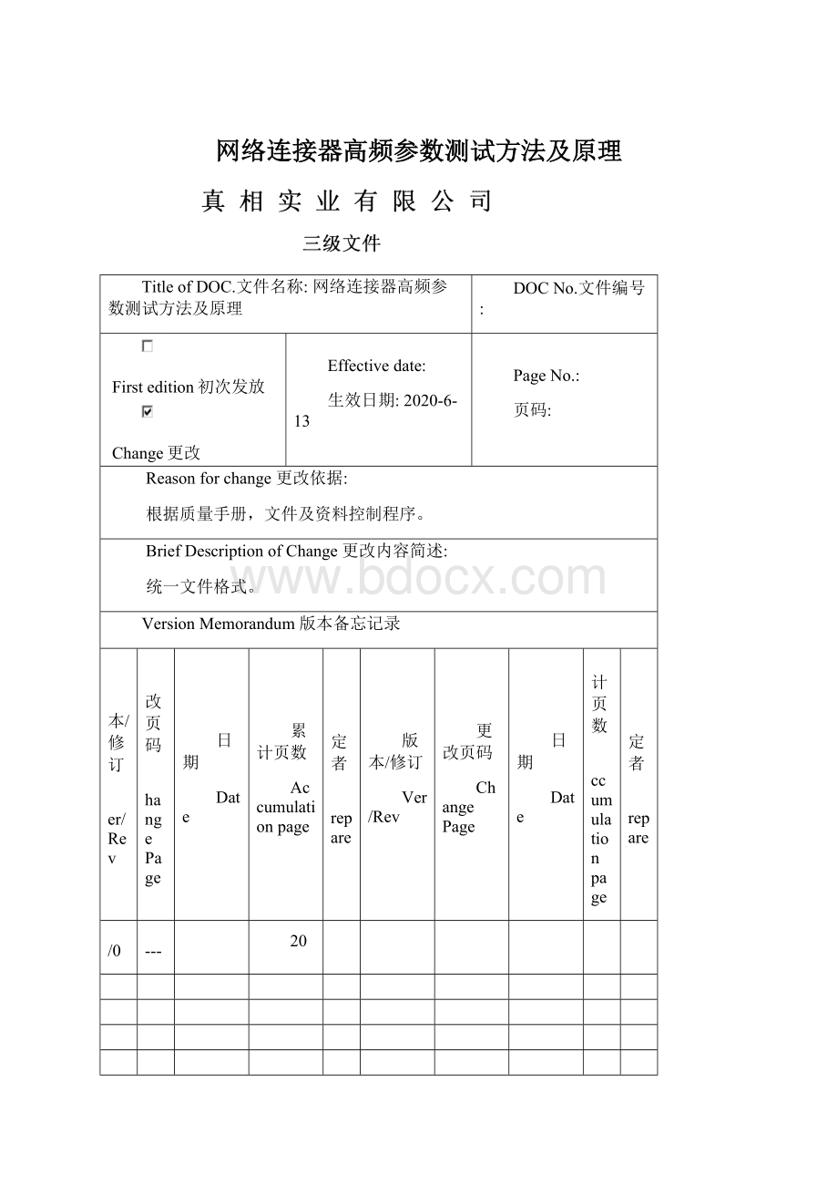
网络连接器高频参数测试方法及原理
TitleofDOC.文件名称:
网络连接器高频参数测试方法及原理
DOCNo.文件编号:
Firstedition初次发放
Change更改
Effectivedate:
生效日期:
2020-6-13
PageNo.:
页码:
Reasonforchange更改依据:
根据质量手册,文件及资料控制程序。
BriefDescriptionofChange更改内容简述:
统一文件格式。
VersionMemorandum版本备忘记录
版本/修订
Ver/Rev
更改页码
ChangePage
日期
Date
累计页数
Accumulationpage
制定者
Prepare
版本/修订
Ver/Rev
更改页码
ChangePage
日期
Date
累计页数
Accumulationpage
制定者
Prepare
A/0
----
20
Preparedby制定:
Checkedby审核:
Approvedby批准:
相关单位会签(三级文件无需会签)
市场部
物料部
计划部
工程部
质量部
生产部
行政部
人力资源部
研发部
管理层
文件发放部门(请在下面表格内填写发放部门,此栏由文件制作部门填写)
□市场部
□物料部
□工程部
□计划部
□质量部
□生产部
□行政部
□人力资源部
□研发部
□管理层
□其它
INSERTIONLOSS(IL),RETURNLOSS(RL),NEARENDCROSSTALKNOISEREJECTION(NEXT),DIFFERENTIAL-MODETOCOMMON-MODE,ANDCOMMONMODETOCOMMONMODENOISEREJECTIONTESTPROCEDUREFORLANMAGNETICS
网络连接器的插入损耗、反射损耗、近端串扰噪声抑制、共模与差模的转换、共模噪声抑制的测试程序
1.Introduction
简介
1.1Scope
ThisprocedureappliestoLANMagnetics,suchasdiscrete,RJ45electricalconnectors.
1.1适用范围
这个测试程序适用于网络连接器。
例如:
变压器,共模扼流圈,RJ45电子连接器。
1.2Object
ThisstandarddescribestestmethodstomeasureIL,RL,Near-EndCrosstalk,DMTOCMandCMTOCMinthefrequencydomains.Itisdesignedtoservethepublicinterestthrougheliminatingmisunderstandingsbetweendesigners,producersandinspectors,facilitatinginterchangeabilityandimprovementofproducts.
1.2目的
这个文件讲叙了在频域内插入损耗、反射损耗、近端串扰、共模与差模的转换及共模抑制的测试方法,以便设计者、生产者和检验者更好的相互了解,从而达到更快更好的改善和改良产品的目的。
1.3Definitions
定义
1.3.1Stimulussignal激励源(信号源)
Withthefrequencydomainmethod,thestimulussignalissinusoidal.
用频域分析法,激励源是正弦曲线。
1.3.2CommonModeImpedance(Z)
Theimpedancemeasuredbetweentheinputandtheoutputofanetwork.Thisismeasuredwithalltheinputsshortedandalltheoutputsshorted.ThisCMimpedancereducesthenoiseenergythatcausesEMI.Theresultingimpedanceinthesignalpathshouldnotmodifythesignal.
1.3.2共模阻抗
共模阻抗是指一个网络输入与输出之间的阻抗,测试时需将所有的输入输出分别短路。
共模阻抗能够减弱引起电磁干扰的噪声。
在信号传输路径上产生的阻抗不应该影响这个信号。
1.3.3CommonModeSignal
Thesignalthatisinphaseonbothsignallines.ThisresultsinEMI.EMIcaneitherberadiatedorconducted(intothepowerline).Commonmodesignalsindigitalterminalequipmentarecreatedbyimbalancesinthesignaltransmissionorintheconversionofdifferentialmodesignalsbyimpedancemismatches.
1.3.3共模信号
共模信号是指在两输入端输入极性相同的信号。
共模信号将导致电磁干扰。
电磁干扰分为辐射干扰和传导干扰(进入电源线内)。
信号传输不对称和阻抗不匹配时差模信号转换都将产生数字终端设备的共模信号。
1.3.4DifferentialModeSignal
Thedatathatisbeingsent.Thesesignalsareofequalamplitudeandoutofphase,thusnoradiationoccurs.
1.3.4差模信号
差模信号是指在两输入端输入大小相等极性相反的信号,它不会产生辐射。
1.3.5ElectroMagneticInterference(EMI)
EMIrepresentsunwantedsignalsthatareradiatedorconductedtosusceptiblesignalpathsthusinterferingwiththeproperfunctionandperformanceofthetransmission.
1.3.5电磁干扰
电磁干扰是指无用信号辐射或传导至敏感的信道,从而引起传播信道的功能和性能的下降。
1.3.6InsertionLoss
Insertionlossisthedecreaseinpowerdeliveredtotheloadwhenafilterisinsertedbetweenthesourceandtheload.Thefigurebelowshowsthetestingsetup.
插入损耗
插入损耗是指一个滤波器插入在电源与负载之间时信号能量的衰减.下图显示了插入损耗测试方法.
IL=20lg
(dB)
1.3.7ReturnLoss
Returnlossisameasureofdissimilarityormismatchbetweenameasuredimpedanceandstandardimpedance,bothinmagnitudeandphaseangle.Thismeasurementisexpressedindecibels(dB).Returnlossisexpressedas
反射损耗
反射损耗是用来描述实测阻抗与标准阻抗不同或不匹配的程度,不同和不匹配既包括幅值大小的不同又包括相位角的不同。
反射损耗的单位是分贝,反射损耗的表达式如下:
WhereZSisthestandardimpedanceandZMismeasuredimpedance.Foraperfectmatch,thereturnlosswouldbeinfinite.
这里ZS是指标准阻抗,ZM是实测阻抗。
如果匹配理想,反射损耗将会无穷大。
1.3.8Crosstalk(NearEndCrosstalkNoiseRejection(NEXT)串扰(近端串扰抑制)
Crosstalkmeasuresundesirableenergycoupledonasignalpathfromanothernearbysignalpath.Thevalueisexpressedindecibels(dB)asaratioofcoupledvoltageonasusceptiblecabletothevoltageonanearbysource.
串扰是指一个通道的无用信号耦合进邻近的信号通道。
串扰的单位是分贝,它是敏感电缆的耦合电压与邻近干扰源电压之比。
1.3.9DCMR(DMTOCMConversion)
共模与差模的转换
Theratio(indB)ofthevoltagerequiredtogenerateastandardoutputfromadifferentialbalancedsystem,whenappliedbetweentheinputports,tothevoltagerequiredtogeneratethesameoutput,whenappliedtobothinputs(shortedtogether)withreferencetothesystemcommonground.
共模与差模的转换是指差模信号的增益与共模信号的增益之比,其单位是分贝。
1.3.10CMRR(Commonmoderejectionratio)
共模抑制比
1.3.11CMA(CMtoCMAttenuation)
共模衰减
CMAisusedtodenoteadecreaseincommonmodesignalmagnitudeintransmissionfromonepointtoanother.AttenuationisexpressedasscalarratiooftheoutputmagnitudetotheinputmagnitudeandisexpressedindB.
共模噪声抑制是用来表示减弱共模信号(从一端传到另一端)大小的能力。
衰减是表示输出信号大小与输入信号大小的比率,它的单位是分贝。
2.Equipmentandtestaccessories.
仪器和测试治具
2.1Equipment
仪器
RFnetworkanalyzerisneededforthetestinthefrequencydomain.EitherHP8712ET/Agilent8753/EN5061AorequivalentisavailableforthemeasurementofIL,RL,Crosstalk,DMTOCM,CMTOCMandsoon.
频域测试就用射频网络分析仪。
像惠普的8712ET、安捷伦的8753、EN5061A或者其它公司同等功能的仪器,它们都可用来测试插入损耗、回损、串扰、阻抗匹配、共模噪声抑制等等。
●Equipment:
Agilent8712ETRFNetworkAnalyzer
仪器:
安捷伦的8712ET射频网络分析仪
●AgilentE5061A300k-1.5GHzENASeriesNetworkAnalyzer
安捷伦的E5061A300k-1.5GHzENA系列的网络分析仪
2.2OnepairofcoaxialcablesendedupwithBNCmaleconnector(50ohm)
一对带BNC公端子(50欧姆)的同轴电缆。
2.3OnepairofcoaxialcablesendedupwithSMAmaleconnector(50ohm)
一对带SMA公端子(50欧姆)的同轴电缆。
2.4Onepairofunbalanced-to-balancedtransformer,50:
100ohmimpedance
50:
100的匹配器
EitherNorthHills0300BB(100KHz-100MHz)orNorthHillsNH13734(100KHz-300MHz)isavailableorSpecialMini-circuitsbaluntransformer.
可以用NorthHills的0300BB(100KHz-100MHz)或者NorthHills的NH13734(100KHz-300MHz)或者是小型的不平衡变压器。
Each1piecefor4channels
2.5Apieceoflogarithmicbaluntransformer:
NorthHillsTSM988210322BF0.1~100MHz,50:
100ohmimpedance.
一个不平衡“镜像”匹配器:
NorthHills的TSM988210322BF0.1~100MHz,阻抗比是
50:
100
2.6ApieceofRJ45plugterminatedwitha100ohmresistoroneachchannel.
一个每个通道带一个100欧姆电阻的RJ45插头
3Testprocedure
测试程序
3.1InsertionRoss
插入损耗
3.1.1Calibration
校准仪器
●SetupSparameterasS21.Makea“though”calibrationtest,asfollows:
设定S参数为S21,然后作“直通”校机,如下图所示:
●Aftercalibration,thescreenshows0dBtyp.
校准以后,屏幕会显示一条曲线,这条曲线的典型值是0dB。
3.1.2ILTest
插入损耗测试
●BlockDiagram方块图
●Connecttheanalyzerstimulusport(Left)tochipsideofthemagneticcircuitandtheresponseport(Right)oftheanalyzertocablesideofthemagneticcircuit.
网络分析仪的激励端(左端)连接磁性电路的chip端;
网络分析仪的响应端(右端)连接磁性电路的cable端。
●Testthespecimen(DUT)asperthecustomerdrawing.
根据客户的图纸测试我们的产品。
3.2ReturnLoss
反射损耗
3.2.1Calibration
校准仪器
●SetupSparameterasS11.Calibratethereflectionport(S11)withthetestfixture
(cable,baluntransformer,RJ45plug)included.asfollows:
设定S参数为S11,然后利用一些治具(电缆、不平衡变压器、RJ45插头)校准反射端(S11)作“开路,短路,加载”校机,如下图所示:
a.Open(connectnothing)
开路测试(什么都不连接)
b.Short(Shortcircuitthesignalpair)
短路测试(将测试两端短路)
c.Load(Connecta100ohmresistortothesignalpair)
加载(在测试两端连接一个100欧姆的电阻)
●Aftercalibration,thescreenshouldshowaflatRLlessthan-40dB,typically-50~-60dB.
校准以后,屏幕应该显示一条平滑的反射损耗曲线,这条曲线应该小于-40dB,一般是-50——-60dB.
3.2.2RLTest
反射损耗测试
●BlockDiagram方块图
●Attacha100ohmresistoronthechipsideofthemagneticcircuit.
在磁性电路的chip端加一个100欧姆的电阻。
●Connecttheanalyzerstimulusporttothecablesideofthemagneticcircuit.
网络分析仪的激励端(左端)连接磁性电路的cable端。
3.3Crosstalk(NearEndCrosstalk(NEXT)
串扰(近端串扰)
3.3.1MaketheS21thrucalibrationtest.
做直通校机测试.
●Cal–Calibrate–Response(Thru)–Thru–Done)
按“Cal”键进入菜单Calibrate/Response(Thru),连接匹配器(如下图)依次按按键“Thru”,“Done”完成校准。
Aftercalibration,theresponsevalueis0dB.
校准后,显示测试值为0dB.
3.3.2ConnecttheRJ45plugtotheanalyzer.
连接RJ45插头到分析仪。
3.3.3TaketheRJ45plugtoperformNEXTtestattwochannels(i.eRJ3-6/4-5)andstorethetestcurveinthememory.
测试连接两个通道(如RJ3-6/4-5)的RJ45插头的曲线,并将此曲线保存到内存。
●Display–DisplayData–Data&MEM–DatatoMEM
进入菜单Display/DisplayData选择Data&Mem后确定退回到Display菜单按”Data→Mem”按键将曲线保存到内存。
3.3.4InsertRJ45plugintotheconnectorterminatedwith100ohmresistorinthechip-sidepins(v.sRJ3-6/4-5)
将RJ45插头插入到被测产品上,在被测产品的芯片端的引脚(如RJ3-6/4-5)接上100Ω的电阻
3.3.5GetthepreliminaryNEXTtestdataoftheconnector.
测得一个近端的串扰曲线。
3.3.6Performthedatamathbetweenthememorydataandthemeasureddata.Here,thepurposeistosubtractthememorytracefromthedatatraceandstoretheresultinthedatatrace.
将测得的曲线与存于内存的曲线相减,得到一条被测产品的实际串扰曲线。
●DataMath–Data-MEM
执行菜单DataMath下的”Data-Mem”按键。
3.3.7ForanexampleofNEXTtesting:
a.Considerthefollowingmagneticcircuitx14asanexample.For10/100Base-Tpart,weshouldattacha100ohmresistorontoRJ1-2&RJ3-6,andthenconnecttheanalyzerstimulusporttothePin11-10andthereceiverportoftheanalyzertothepin4-5.ItmeansthenextendcrosstalkofRJ1-2vsRJ3-6.
拿下面的磁性电路x14为例来说明一下。
10/100Base-T部分,我们应该在RJ1-2和RJ3-6端各连一个100欧姆的电阻,然后网络分析仪的激励端连Pin11-10,网络分析仪的接收端连pin4-5。
也就是说近端串扰就是RJ1-2和RJ3-6之间。
b.ConsiderfollowingmagneticcircuitG18asanexample.For10/100/1000(Gigabit)part,weshouldtestandrecordthenearendcrosstalkdataasfollows:
拿下面的磁性电路G18为例来说明一下。
10/100/1000(Gigabit)部分,我们应该测试
纪录近端终端串扰的数据
1)RJ1-2v.s.RJ3-6
2)RJ3-6v.sRJ4-5
3)RJ4-5v.sRJ7-8
1)RJ1-2与RJ3-6之间的串扰数据。
2)RJ3-6与RJ4-5之间的串扰数据。
3)RJ4-5与RJ7-8之间的串扰数据。
c.Testthespecimen(DUT)asperthecustomerdrawing
根据客户的图纸来测试我们的产品。
3.4CMRR
3.4.1Calibration
校准
●Makethesa
- 配套讲稿:
如PPT文件的首页显示word图标,表示该PPT已包含配套word讲稿。双击word图标可打开word文档。
- 特殊限制:
部分文档作品中含有的国旗、国徽等图片,仅作为作品整体效果示例展示,禁止商用。设计者仅对作品中独创性部分享有著作权。
- 关 键 词:
- 网络 连接器 高频 参数 测试 方法 原理
 冰豆网所有资源均是用户自行上传分享,仅供网友学习交流,未经上传用户书面授权,请勿作他用。


 《雷雨》中的蘩漪人物形象分析 1.docx
