 Finite Element Analysis Report for Drying Raw Mill new.docx
- 文档编号:30692614
- 上传时间:2023-08-19
- 格式:DOCX
- 页数:13
- 大小:688.12KB
Finite Element Analysis Report for Drying Raw Mill new.docx
《Finite Element Analysis Report for Drying Raw Mill new.docx》由会员分享,可在线阅读,更多相关《Finite Element Analysis Report for Drying Raw Mill new.docx(13页珍藏版)》请在冰豆网上搜索。
FiniteElementAnalysisReportforDryingRawMillnew
FiniteElementAnalysisReportforDryingRawMill
1.Introduction
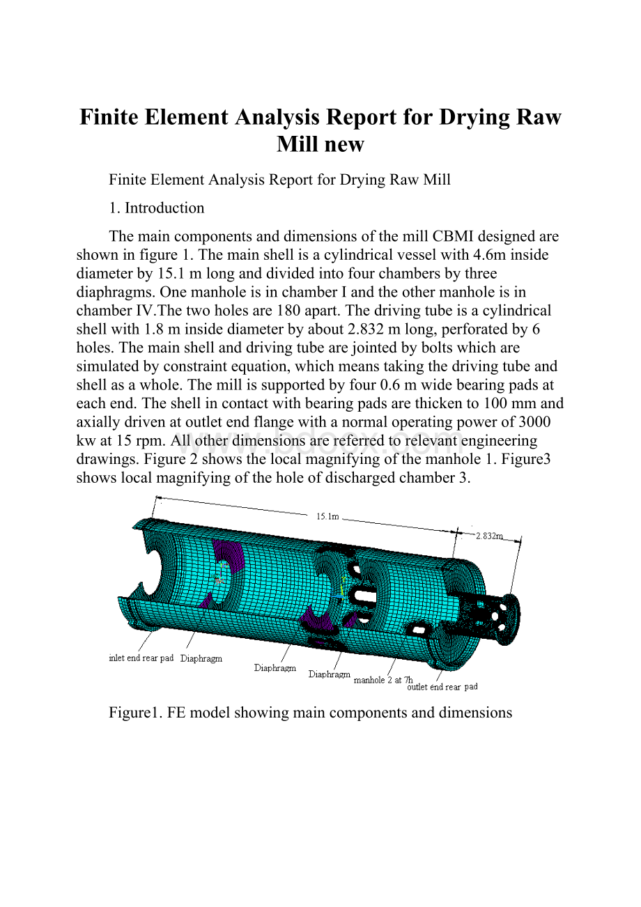
ThemaincomponentsanddimensionsofthemillCBMIdesignedareshowninfigure1.Themainshellisacylindricalvesselwith4.6minsidediameterby15.1mlonganddividedintofourchambersbythreediaphragms.OnemanholeisinchamberIandtheothermanholeisinchamberⅣ.Thetwoholesare180apart.Thedrivingtubeisacylindricalshellwith1.8minsidediameterbyabout2.832mlong,perforatedby6holes.Themainshellanddrivingtubearejointedbyboltswhicharesimulatedbyconstraintequation,whichmeanstakingthedrivingtubeandshellasawhole.Themillissupportedbyfour0.6mwidebearingpadsateachend.Theshellincontactwithbearingpadsarethickento100mmandaxiallydrivenatoutletendflangewithanormaloperatingpowerof3000kwat15rpm.Allotherdimensionsarereferredtorelevantengineeringdrawings.Figure2showsthelocalmagnifyingofthemanhole1.Figure3showslocalmagnifyingoftheholeofdischargedchamber3.
Figure1.FEmodelshowingmaincomponentsanddimensions
Figure2.localmagnifyingofthemanhole1
Figure3.localmagnifyingoftheholeofdischargedchamber3
2.Boundaryconditions
3-Dstructureelementandquadraticshellelementareusedtomodelthemill.
2.1Drivingtorqueandoffsetload
AdrivingtorqueT=1910000N.mwhichcorrespondstoabout3000kwat15rpmisappliedbycircumferentialforcesonendflange.Aloadof200736.3kginternalballsandmaterialisappliedasadditionalmassonbottompartofmainshellandoffsettotheleftasillustratedinfigure4.TheangularpositionsofAandBareapproximately-1800and-600respectively,foundbytrialanderrorsoastocounterbalancetheappliedadditionalmass.
Figure4.Drivingtorqueandoffsetload
Figure5Modelof8supportpads
2.2Linermasses
7559kgforheadlineratinletend,7942kgforheadlineratoutletend,14782.56kgforshelllinerinchamberI,38088kgforshelllinerinchamberⅡ,10760kgforshelllinerinchamberⅢ,22954kgforshelllinerinchamberⅣareappliedasadditionaldistributedmassofcorrespondingcomponents(headplatesandmainshell).
2.3Diaphragm
16402kgweightfordiaphragmbetweenchamberIandⅡ,8201kgweightforthetwodiaphragmsrespectivelyindischargedchamberⅢ,alltheweightsareappliedasdistributedmassofanannularplateusingverysmallYoung'smodulussothatthediaphragmdoesnotcontributetothestiffnessoftheshell.
2.4Drivingtubeandshellmasses
12399kgfordrivingtube(SeedrawingNO.BMRaCD46.3.7),122683kgforshell(SeedrawingNO.BMRaCD4685/35.3.4),alloftheweightswillbecalculatedbydefiningdenseofthematerialthroughANSYSsystem,andultimatelyappliedtothemodel.
2.5Support
Thecontactmodelisintroducedtosimulatethefrictionlesscontactbetweenshellringsandthe200mmthicksupportpads.Radialreactionsillustrateinfigure5.
Totally,12modelsarestudied,eachoneforeveryhourpositioninaccordingtothepositionofpads,andonlyimportantandcriticalresultsarereportedbelow.
3.Resultanalysis
3.1Resultsforforcesandstressesonpads
Asillustratedinfigure5andthroughcontactmodelsimulation,
=551380,
=592676,
=666763N,
=964697N,
=581772N,
=557564N,
=581077N,
=948661N,finallytheverticalreactiontotallyequalsto4697300N(about479.36tons).
With0.2mthickplatesforpads,themaximumVonMisesstressis7.57MPa(figure6).Foranyotherthicknessofpads,byfunction
=
inMPaandtinmeter,basedonthefactthatbendingstressinplatesisinverselyproportionaltothesquareofitsthickness(
=
).Usingtheyieldstrength185MPaofthepadsmaterialandsafetyfactor2,thefunctiongivesthethicknessofpadsis57mm.
Figure6ThemaximumVonMisesstressinpads
Padshaveasafetyfactorgreaterthan2whiletheyarestrongerthan57mmthickplate.
3.2Maximumstressindrivingtube
Asillustratedinfigure7,"TheVonMisesstressdistributionofdrivingtube"showsthemaximumVonMisesstressis17.6MPa.Consideringthestartuptorque2.5timesgreater,thenthesafetyfactoragainstyieldis200/17.6/2.5=4.54.Figure8showsthemaximumVonMisesstressofdrivingtubehole,whichis4.17MPa,muchsmallerthanthematerialbreakagelimit.
Figure7TheVonMisesstressdistributionofdrivingtube
Figure8TheVonMisesstressdistributionofdrivingtubehole
3.3stressanalysisofmanholes
3.3.1VonMisesstressaroundmanhole
Formanhole1,themaximumstaticVonMisesstressis66.7MPaat4hposition(seeFig9);formanhole2,themaximumstaticVonMisesstressis79.4MPaat4hposition(seeFig10);thesafetyfactorwithrespecttoyieldisf=250/79.4=3.15
Fig9MaximumVonMisesStressaroundmanhole1
Fig10MaximumVonMisesStressaroundmanhole2
3.3.2Fatiguestressaroundmanhole
Formanhole1,theworstprincipalstressrangeoccursontheedgeofshellbetween
maxat4h=68.4Mpaand
minat7h=-12.9Mpa(Fig11-12).Thus,stressrange=68.4-(12.9)=81.3Mpa.SafetyfactorwithrespecttoallowableinfinitelifecategoryAstressaccordingtoAISC:
f=165(Mpa)/(81.3Mpa)=2.02。
Fig11Max.principalstressonmanhole1
Fig12Min.principalstressonmanhole1
Formanhole2,theworstprincipalstressrangeoccursontheedgeofshellbetween
maxat10h=82.1Mpaand
minat2h=-19.7Mpa(Fig13-14).Thus,stressrange=82.1-(19.7)=101.8Mpa.SafetyfactorwithrespecttoallowableinfinitelifecategoryAstressaccordingtoAISC:
f=165(Mpa)/(101.8Mpa)=1.62。
Fig13Max.principalstressonmanhole2
Fig14Min.principalstressonmanhole2
3.4Fatiguestressarounddischargedhole
Forthesymmetricalcharacteristicsoftheholeinthedischargedpart,thisreportjuststudiesoneholewiththesamepositionofmanhole1ofeveryhourposition.
Forthedischargedhole,theworstprincipalstressrangeoccursontheedgeofinsideshellbetween
maxat4h=45.5Mpaand
minat10h=-14.7Mpa(Fig15-16).Thus,stressrange
=45.5-(-14.7)=60.2Mpa.SafetyfactorwithrespecttoallowableinfinitelifecategoryAstressaccordingtoAISC:
=(165Mpa)/(60.2Mpa)=2.74
Fig15Max.principalstressondischargedhole
Fig16Min.principalstressondischargedhole
3.5Fatiguestressof“T”shapebuttjoint
Forthesymmetricalcharacteristicsofsliderring,takeonesideofthe“T”shapebuttjointinthepositionofinletendforexample.Theworstprincipalstressrangeoccursontheedgeofshellbetween
maxat1h=2.35Mpaand
minat3h=-9.5Mpa(Fig17-18).Thus,stressrange
=2.35-(-9.5)=11.85Mpa.SafetyfactorwithrespecttoallowableinfinitelifecategoryAstressaccordingtoAISC:
=(165Mpa)/(11.85Mpa)=13.92
Fig17Max.principalstressof“T”shapebuttjoint
Fig18Min.principalstressof“T”shapebuttjoint
4Generalconlusions
1.Thesafetyfactorwithrespecttoyieldofmanholesandmainshell=3.15whichmeetthestrengthrequirement.
2.Formanhole1,fatiguestressrange=81.3Mpa,safetyfactor=2.02;formanhole2,fatiguestressrange=101.8Mpa,safetyfactor=1.62;fordischargedhole,fatiguestressrange=60.2Mpa,safetyfactor=2.74.For“T”shapebuttjoint,fatiguestressrange=11.85Mpa,safetyfactor=13.92.Thefatiguestrengthofmanholesmeetdesignrequirement.
3.Themaximumstressondrivingtube=17.6Mpa,consideringthestartuptorque2.5timesgreater,safetyfactor=4.54,whicharesafeenough.
4.ThemaximumVonMisesstressofbearingpads=7.57Mpa.ThemaximumVonMisesstressofthecontactsurfaceofsliderring=10.0Mpa.
Inaword,thedesignofmillmeetsstaticandfatiguerequirement.


- 配套讲稿:
如PPT文件的首页显示word图标,表示该PPT已包含配套word讲稿。双击word图标可打开word文档。
- 特殊限制:
部分文档作品中含有的国旗、国徽等图片,仅作为作品整体效果示例展示,禁止商用。设计者仅对作品中独创性部分享有著作权。
- 关 键 词:
- Finite Element Analysis Report for Drying Raw Mill new
 冰豆网所有资源均是用户自行上传分享,仅供网友学习交流,未经上传用户书面授权,请勿作他用。
 #2机组现场施工用电布置措施.docx
-
《个人贵金属质押借款合同》兴业银行.docx
-
《科学发展观和小康社会的经济建设》复习导学案.docx
-
《我和祖父的园子》第一课时教案两篇word.docx
-
《质量》教学案例与设计.docx
-
2惠农小册子.docx
-
7A版个人与团队模拟考试题及答案.docx
-
10篇新部编四年级下册语文课内外阅读理解专项练习题及答案.docx
-
16初四物理热和能知识点总结精讲.docx
-
20XX社会语言经典语录流行风暴.docx
-
48篇教学案例分析报告题.docx
-
《电子工厂安全管理制度汇总》.docx
-
《机械制造课程设计》指导.docx
-
《钱学森》教案第二课时.docx
-
《边城》读后感5篇.docx
-
《固定式压力容器安全技术监察规程》.docx
-
《论雷峰塔的倒掉》.docx
-
《手术台就是阵地》教学设计三年级语文下册.docx
-
《夏洛的网》课外阅读教学设计.docx
-
《自己的花是让别人看的》教案.docx
-
3C检查表090429.docx
-
7客运专线CRTSⅡ型板式无砟轨道施工工法.docx
-
《笔算除法》课时教案设计.docx
-
11#楼高大模板支撑体系专项方案.docx
-
17科学分析经济形势.docx
-
《电流和电路》易错题精讲综合检测题与答案.docx
-
《会计信息系统》习题含答案.docx
-
《汽车电器设备与维修》发电机分教考分离试题及标准答案.docx
-
《四川省排污许可证管理暂行办法》.docx
-
《新编实用英语》教案第一册Unit.docx
-
0母版锅炉值班员计算题WORD版.docx
-
3年级下册英语单词记忆人教版.docx
-
新冠肺炎防控制度汇编 1.docx
-
完整升级版渝北区建筑垃圾消纳场土建工程施工组织设计.docx
-
十位数加减法练习题#精选.docx
-
新建铁路兰州至重庆线某隧道测量控制方案.docx
-
微生物试验室安全管理制度复习过程.docx
-
小班餐桌礼仪的教案.docx
-
新能源创业计划书.docx
-
实习感受精选20篇.docx
-
为自己竖起大拇指作文600字初一优秀10篇.docx
-
小班下学期班级个人工作计划.docx
-
新人教版小学10以内加减法练习题500道.docx
-
文化产业化的后果.docx
-
小户型设计方案说明.docx
-
实验室工作计划.docx
-
我的自画像四年级作文精选.docx
-
小区室外消防管道施工组织设计.docx
-
星三角启动.docx
-
实用参考儿童歌曲简谱大全.docx
-
企业家座谈会主持词及会议流程参考.docx
链接地址:https://www.bdocx.com/doc/30692614.html
