 Lab 42 InterVLAN Routing with an Internal Route Processor and.docx
- 文档编号:30132998
- 上传时间:2023-08-05
- 格式:DOCX
- 页数:24
- 大小:86.29KB
Lab 42 InterVLAN Routing with an Internal Route Processor and.docx
《Lab 42 InterVLAN Routing with an Internal Route Processor and.docx》由会员分享,可在线阅读,更多相关《Lab 42 InterVLAN Routing with an Internal Route Processor and.docx(24页珍藏版)》请在冰豆网上搜索。

Lab42InterVLANRoutingwithanInternalRouteProcessorand
Lab4-2Inter-VLANRoutingwithanInternalRouteProcessorand
MonitoringCEFFunctions
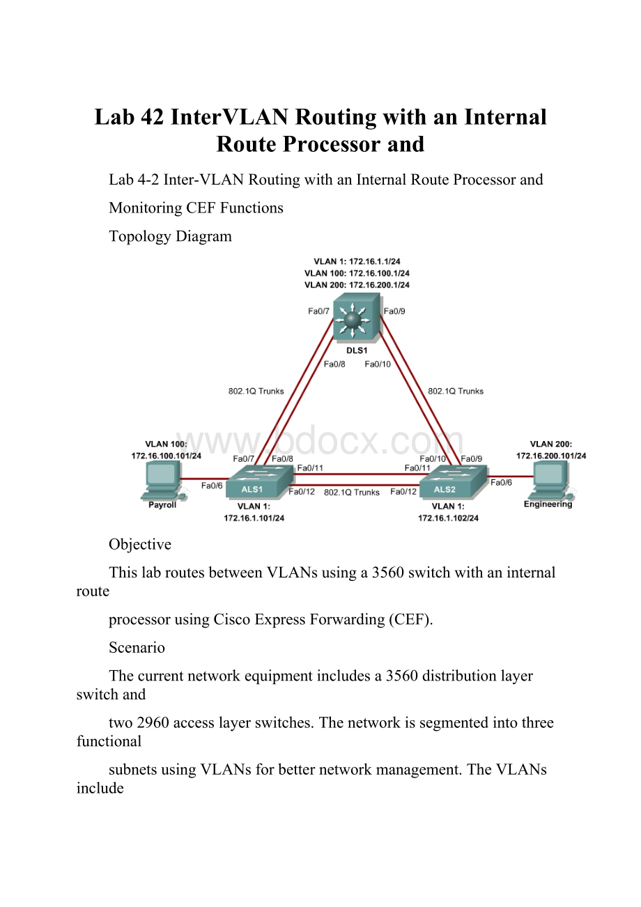
TopologyDiagram
Objective
ThislabroutesbetweenVLANsusinga3560switchwithaninternalroute
processorusingCiscoExpressForwarding(CEF).
Scenario
Thecurrentnetworkequipmentincludesa3560distributionlayerswitchand
two2960accesslayerswitches.Thenetworkissegmentedintothreefunctional
subnetsusingVLANsforbetternetworkmanagement.TheVLANsinclude
Finance,Engineering,andasubnetforequipmentmanagement,whichisthe
defaultmanagementVLAN,VLAN1.AfterVTPandtrunkinghavebeen
configuredfortheswitches,SwitchedVirtualInterfaces(SVI)areusedonthe
distributionlayerswitchtoroutebetweentheseVLANs,givingfullconnectivity
totheinternalnetwork.
2-13CCNP:
BuildingMultilayerSwitchedNetworksv5.0-Lab4-2Copyright©2006,CiscoSystems,Inc
Step1
Poweruptheswitchesandusethestandardprocessforestablishinga
HyperTerminalconsoleconnectionfromaworkstationtoeachswitchinyour
pod.Ifyouareremotelyaccessingyourequipment,followyourteacher’s
instructions.
RemoveallVLANinformationandconfigurationsthatwerepreviouslyentered
intoyourswitches.(RefertoLab2.0aor2.0bifneeded.)
Step2
Cablethelabaccordingtothediagram.Configurethehostname,password,
andtelnetaccessoneachswitch.
Thefollowingisasampleconfigurationforthe2960switchALS1:
Switch#configureterminal
Enterconfigurationcommands,oneperline.EndwithCNTL/Z.
Switch(config)#hostnameALS1
ALS1(config)#enablesecretcisco
ALS1(config)#linevty015
ALS1(config-line)#passwordcisco
ALS1(config-line)#login
ALS1(config-line)#end
Thefollowingisasampleconfigurationforthe2960switchALS2:
Switch#configureterminal
Enterconfigurationcommands,oneperline.EndwithCNTL/Z.
Switch(config)#hostnameALS2
ALS2(config)#enablesecretcisco
ALS2(config)#linevty015
ALS2(config-line)#passwordcisco
ALS2(config-line)#login
ALS2(config-line)#end
Thefollowingisasampleconfigurationforthe3560switchDLS1:
Switch#configureterminal
Enterconfigurationcommands,oneperline.EndwithCNTL/Z.
Switch(config)#hostnameDLS1
DLS1(config)#enablesecretcisco
DLS1(config)#linevty015
DLS1(config-line)#passwordcisco
DLS1(config-line)#login
DLS1(config-line)#end
ConfiguremanagementIPaddressesonVLAN1forallthreeswitches
accordingtothediagram.
Thefollowingisasampleconfigurationforthe2960switchALS1:
ALS1#configureterminal
Enterconfigurationcommands,oneperline.EndwithCNTL/Z.
ALS1(config)#interfacevlan1
3-13CCNP:
BuildingMultilayerSwitchedNetworksv5.0-Lab4-2Copyright©2006,CiscoSystems,Inc
ALS1(config-if)#ipaddress172.16.1.101255.255.255.0
ALS1(config-if)#noshutdown
ALS1(config-if)#exit
Thefollowingisasampleconfigurationforthe2960switchALS2:
ALS2#configureterminal
Enterconfigurationcommands,oneperline.EndwithCNTL/Z.
ALS2(config)#interfacevlan1
ALS2(config-if)#ipaddress172.16.1.102255.255.255.0
ALS2(config-if)#noshutdown
ALS2(config-if)#exit
Thefollowingisasampleconfigurationforthe3560switchDLS1:
DLS1#configureterminal
Enterconfigurationcommands,oneperline.EndwithCNTL/Z.
DLS1(config)#interfacevlan1
DLS1(config-if)#ipaddress172.16.1.1255.255.255.0
DLS1(config-if)#noshutdown
DLS1(config-if)#exit
Configuredefaultgatewaysontheaccesslayerswitches.Thedistributionlayer
switchwillnotuseadefaultgateway,becauseitactsasaLayer3device.The
accesslayerswitchesactasLayer2devicesandneedadefaultgatewayto
sendtrafficoffofthelocalsubnetforthemanagementVLAN.
Thefollowingisasampleconfigurationforthe2960switchALS1:
ALS1#configureterminal
Enterconfigurationcommands,oneperline.EndwithCNTL/Z.
ALS1(config)#ipdefault-gateway172.16.1.1
ALS1(config-line)#end
Thefollowingisasampleconfigurationforthe2960switchALS2:
ALS2#configureterminal
Enterconfigurationcommands,oneperline.EndwithCNTL/Z.
ALS2(config)#ipdefault-gateway172.16.1.1
ALS2(config-line)#end
Step3
ConfiguretrunksandEtherChannelsbetweenswitches.
TodistributeVLANandVTPinformationbetweentheswitches,trunksare
neededbetweenthethreeswitches.Configurethesetrunksaccordingtothe
diagram.EtherChannelisusedforthesetrunks.EtherChannelallowsyouto
utilizebothFastEthernetinterfacesthatareavailablebetweeneachdevice,
therebydoublingthebandwidth.
ThefollowingisasampleconfigurationforthetrunksandEtherChannelfrom
DLS1toASL1.Theswitchporttrunkencapsulation[isl|dot1q]commandis
usedbecausethisswitchalsosupportsISLencapsulation.
4-13CCNP:
BuildingMultilayerSwitchedNetworksv5.0-Lab4-2Copyright©2006,CiscoSystems,Inc
DLS1#configureterminal
Enterconfigurationcommands,oneperline.EndwithCNTL/Z.
DLS1(config)#interfacerangefastethernet0/7-8
DLS1(config-if-range)#switchporttrunkencapsulationdot1q
DLS1(config-if-range)#switchportmodetrunk
DLS1(config-if-range)#channel-group1modedesirable
Creatingaport-channelinterfacePort-channel1
ThefollowingisasampleconfigurationforthetrunksandEtherChannelfrom
DLS1toASL2:
DLS1#configureterminal
Enterconfigurationcommands,oneperline.EndwithCNTL/Z.
DLS1(config)#interfacerangefastethernet0/9-10
DLS1(config-if-range)#switchporttrunkencapsulationdot1q
DLS1(config-if-range)#switchportmodetrunk
DLS1(config-if-range)#channel-group2modedesirable
Creatingaport-channelinterfacePort-channel2
ThefollowingisasampleconfigurationforthetrunksandEtherChannel
betweenALS1andDLS1,andforthetrunksandEtherChannelbetweenALS1
andALS2:
ALS1#configureterminal
Enterconfigurationcommands,oneperline.EndwithCNTL/Z.
ALS1(config)#interfacerangefastethernet0/11-12
ALS1(config-if-range)#switchportmodetrunk
ALS1(config-if-range)#channel-group1modedesirable
Creatingaport-channelinterfacePort-channel1
ALS1(config-if-range)#exit
ALS1(config)#interfacerangefastethernet0/7-8
ALS1(config-if-range)#switchportmodetrunk
ALS1(config-if-range)#channel-group2modedesirable
Creatingaport-channelinterfacePort-channel2
ThefollowingisasampleconfigurationforthetrunksandEtherChannel
betweenALS2andDLS1,andforthetrunksandEtherChannelbetweenALS2
andALS1.
ALS2#configureterminal
Enterconfigurationcommands,oneperline.EndwithCNTL/Z.
ALS2(config)#interfacerangefastethernet0/11-12
ALS2(config-if-range)#switchportmodetrunk
ALS2(config-if-range)#channel-group1modedesirable
Creatingaport-channelinterfacePort-channel1
ALS2(config-if-range)#exit
ALS1(config)#interfacerangefastethernet0/7-8
ALS1(config-if-range)#switchportmodetrunk
ALS1(config-if-range)#channel-group2modedesirable
Creatingaport-channelinterfacePort-channel2
5-13CCNP:
BuildingMultilayerSwitchedNetworksv5.0-Lab4-2Copyright©2006,CiscoSystems,Inc
VerifytrunkingbetweenDLS1,ALS1,andALS2usingtheshowinterface
trunkcommandonallswitches.
DLS1#showinterfacetrunk
PortModeEncapsulationStatusNativevlan
Po1on802.1qtrunking1
Po2on802.1qtrunking1
PortVlansallowedontrunk
Po11-4094
Po21-4094
PortVlansallowedandactiveinmanagementdomain
Po11
Po21
PortVlansinspanningtreeforwardingstateandnotpruned
Po11
Po21
Usetheshowetherchannelsummarycommandoneachswitchtoverifythe
EtherChannels.
ThefollowingissampleoutputfromALS1.NoticethetwoEtherChannelsonthe
accesslayerswitches.
ALS1#showetherchannelsummary
Flags:
D-downP-inport-channel
I-stand-alones-suspended
H-Hot-standby(LACPonly)
R-Layer3S-Layer2
U-inusef-failedtoallocateaggregator
u-unsuitableforbundling
w-waitingtobeaggregated
d-defaultport
Numberofchannel-groupsinuse:
2
Numberofaggregators:
2
GroupPort-channelProtocolPorts
------+-------------+-----------+---------------------------------------------
1Po1(SU)PAgPFa0/11(P)Fa0/12(P)
2Po2(SU)PAgPFa0/7(P)Fa0/8(P)
1.Whichportsareusedforchannelgroup2?
Step4
ChangetheVTPmodeofALS1andALS2toclient.
ALS1#configureterminal
Enterconfigurationcommands,oneperline.EndwithCNTL/Z.
6-13CCNP:
BuildingMultilayerSwitchedNetworksv5.0-Lab4-2Copyright©2006,CiscoSystems,Inc
ALS1(config)#vtpmodeclient
SettingdevicetoVTPCLIENTmode.
ALS1(config)#end
ALS2#configureterminal
Enterconfigurationcommands,oneperline.EndwithCNTL/Z.
ALS2(config)#vtpmodeclient
SettingdevicetoVTPCLIENTmode.
ALS2(config)#end
VerifytheVTPchangeswiththeshowvtpstatuscommand.
ALS2#showvtpstatus
VTPVersion:
2
ConfigurationRevision:
0
MaximumVLANssupportedlocally:
1005
NumberofexistingVLANs:
5
VTPOperatingMode:
Client
VTPDomainName:
VTPPruningMode:
Disabled
VTPV2Mode:
Disabled
VTPTrapsGeneration:
Disabled
MD5digest:
0xC80xAB0x3C0x3B0xAB0xDD0x340xCF
Configurationlastmodifiedby0.0.0.0at3-1-9315:
47:
34
2.HowmanyVLANscanbesupportedlocallyonthe2960switch?
Step5
CreatetheVTPdomainonDLS1andcreateVLANS100and200forthe
domain.
DLS1#configureterminal
Enterconfigurationcommands,oneperline.EndwithCNTL/Z.
DLS1(config)#vtpdomainSWPOD
DLS1(config)#vlan100
DLS1(config-vlan)#nameFinance
DLS1(config-vlan)#exit
DLS1(config)#vlan200
DLS1(config-vlan)#nameEngineering
DLS1(config-vlan)#end
VerifyVTPinformationthroughoutthedomainusingtheshowvlanandshow
vtpstatuscommands.
3.HowmanyexistingVLANsare
- 配套讲稿:
如PPT文件的首页显示word图标,表示该PPT已包含配套word讲稿。双击word图标可打开word文档。
- 特殊限制:
部分文档作品中含有的国旗、国徽等图片,仅作为作品整体效果示例展示,禁止商用。设计者仅对作品中独创性部分享有著作权。
- 关 键 词:
- Lab 42 InterVLAN Routing with an Internal Route Processor and
 冰豆网所有资源均是用户自行上传分享,仅供网友学习交流,未经上传用户书面授权,请勿作他用。
链接地址:https://www.bdocx.com/doc/30132998.html


 #2机组现场施工用电布置措施.docx
