 项目8 数字电压表设计.docx
- 文档编号:29614628
- 上传时间:2023-07-25
- 格式:DOCX
- 页数:10
- 大小:179.11KB
项目8 数字电压表设计.docx
《项目8 数字电压表设计.docx》由会员分享,可在线阅读,更多相关《项目8 数字电压表设计.docx(10页珍藏版)》请在冰豆网上搜索。
项目8数字电压表设计
项目八数字电压计设计
班级:
09电信姓名:
曾珍学号:
33
1.实训目标
1)使用AD0809模数转换芯片实现信号转换。
2)在EDA-V+系统上实现交通灯控制系统。
2.实训步骤
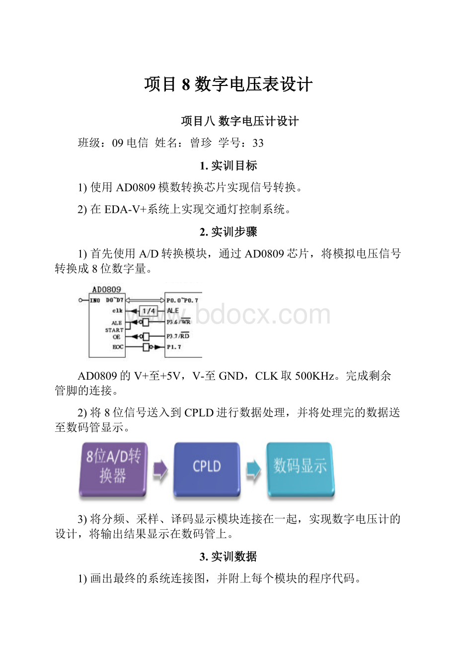
1)首先使用A/D转换模块,通过AD0809芯片,将模拟电压信号转换成8位数字量。
AD0809的V+至+5V,V-至GND,CLK取500KHz。
完成剩余管脚的连接。
2)将8位信号送入到CPLD进行数据处理,并将处理完的数据送至数码管显示。
3)将分频、采样、译码显示模块连接在一起,实现数字电压计的设计,将输出结果显示在数码管上。
3.实训数据
1)画出最终的系统连接图,并附上每个模块的程序代码。
division1
libraryieee;
useieee.std_logic_1164.all;
useieee.std_logic_unsigned.all;
entitydivision1is
port(
clk:
instd_logic;
clk4:
outstd_logic);
enddivision1;
architecturebehaveofdivision1is
begin
process(clk)
variablecounter:
std_logic_vector(7downto0);
begin
if(clk'eventandclk='0')then
if(counter=250)then
counter:
="00000000";
clk4<='1';
else
counter:
=counter+'1';
clk4<='0';
endif;
endif;
endprocess;
endbehave;
code
libraryieee;
useieee.std_logic_1164.all;
useieee.std_logic_unsigned.all;
useieee.std_logic_arith.all;
entitycodeis
port(clk:
instd_logic;
datain:
inunsigned(7downto0);
scan:
outstd_logic_vector(1downto0);
dataout1:
outstd_logic_vector(6downto0)
);
endcode;
architecturebehaveofcodeis
signalcnt:
integerrange2downto0;
signaldata:
integerrange9downto0;
signaltemp1:
integerrange511downto0;
signaltemp2:
integerrange99downto0;
signalcount1,count2:
integerrange9downto0;
signalcount3:
integerrange5downto0;
begin
process(clk)
begin
ifclk'eventandclk='1'then
ifcnt=2thencnt<=0;
else
cnt<=cnt+1;
endif;
endif;
endprocess;
process(datain)
begin
temp1<=conv_integer(datain)+conv_integer(datain);
casetemp1is
when500to511=>
count3<=5;temp2<=temp1-500;
when400to499=>
count3<=4;temp2<=temp1-400;
when300to399=>
count3<=3;temp2<=temp1-300;
when200to299=>
count3<=2;temp2<=temp1-200;
when100to199=>
count3<=1;temp2<=temp1-100;
when0to99=>
count3<=0;temp2<=temp1;
whenothers=>null;
endcase;
casetemp2is
when90to99=>
count2<=9;count1<=temp2-90;
when80to89=>
count2<=8;count1<=temp2-80;
when70to79=>
count2<=7;count1<=temp2-70;
when60to69=>
count2<=6;count1<=temp2-60;
when50to59=>
count2<=5;count1<=temp2-50;
when40to49=>
count2<=4;count1<=temp2-40;
when30to39=>
count2<=3;count1<=temp2-30;
when20to29=>
count2<=2;count1<=temp2-20;
when10to19=>
count2<=1;count1<=temp2-10;
when0to9=>
count2<=0;count1<=temp2;
whenothers=>null;
endcase;
endprocess;
process(cnt)
begin
casecntis
when0=>data<=count1;scan<="00";
when1=>data<=count2;scan<="01";
when2=>data<=count3;scan<="10";
whenothers=>null;
endcase;
endprocess;
process(data)
begin
casedatais
when0=>dataout1<="0111111";
when1=>dataout1<="0000110";
when2=>dataout1<="1011011";
when3=>dataout1<="1001111";
when4=>dataout1<="1100110";
when5=>dataout1<="1101101";
when6=>dataout1<="1111101";
when7=>dataout1<="0000111";
when8=>dataout1<="1111111";
when9=>dataout1<="1101111";
whenothers=>null;
endcase;
endprocess;
endbehave;
ad
libraryieee;
useieee.std_logic_1164.all;
useieee.std_logic_arith.all;
entityadis
port(busy:
instd_logic;
datain:
inunsigned(7downto0);
clk:
instd_logic;
dataout:
outunsigned(7downto0);
cs:
outstd_logic;
rd:
outstd_logic
);
endad;
architecturebehavofadis
begin
process(clk)
variablecount:
unsigned(1downto0);
begin
ifclk'eventandclk='1'then
casecountis
when"00"=>
cs<='1';
rd<='1';
dataout<=datain;
when"01"=>
cs<='0';
rd<='0';
when"11"=>
ifbusy='0'then
count:
=count-1;
endif;
whenothers=>
null;
endcase;
count:
=count+1;
endif;
endprocess;
endbehav;
2)记录下系统的外部连线,注明每个管脚的功能。
芯片EP1K30TC144-3
26~33接datain[7..0]---------输入
54接busy----------------------
55接clk------------------------脉冲信号500khz
92~86接dataout1[6..0]------输出接到数码管显示数字信号
98,99接scan[1..0]------------扫描
101接cs
102接rd
芯片0809
Busy接
Int接54busy
D0~d7接26~33接datain[7..0]
Vref+接vcc
Vref-接gnd
In0接试验箱滑阻
Cs接101cs
Rd接101rd
3)本设计中的数字电压计的最小测量电压值是多少?
拿一块数字万用表同时进行测量,比较数字电压计的误差,并记录相应数据。
4.附AD0809芯片资料
1)芯片结构
2)信号选择段


- 配套讲稿:
如PPT文件的首页显示word图标,表示该PPT已包含配套word讲稿。双击word图标可打开word文档。
- 特殊限制:
部分文档作品中含有的国旗、国徽等图片,仅作为作品整体效果示例展示,禁止商用。设计者仅对作品中独创性部分享有著作权。
- 关 键 词:
- 项目8 数字电压表设计 项目 数字 电压表 设计
 冰豆网所有资源均是用户自行上传分享,仅供网友学习交流,未经上传用户书面授权,请勿作他用。
 《贝的故事》教案4.docx
-
《对韵歌》优秀教案8.docx
-
《函数yAsinωx+φ+P图象》wwwnet.docx
-
《静夜思》教学设计.docx
-
《汽车底盘构造与维修》题库与考核标准.docx
-
《世说新语》复习资料.docx
-
《我的服装我做主》教案设计.docx
-
《在品味情感中成长》教学片断设计.docx
-
11造价员《建设工程造价管理基础知识》精讲教程文件.docx
-
《不会叫的狗》教案 人教部编版1.docx
-
《操作系统》二学期A卷及答案.docx
-
《傅雷家书》名著阅读笔记.docx
-
《反不正当竞争法》下互联网平台封禁行为考辨以消费者用户合法权益保护为中心.docx
-
《化工原理》第六章蒸发.docx
-
《蓝海战略》概要11页.docx
-
《人生》读书心得.docx
-
《荷叶圆圆》公开课教案优秀教学设计26.docx
-
《科技出行研究报告》智能网联与新能源将变革未来汽车出行.docx
-
《272 向量的应用举例》导学案1.docx
-
《秋天》评课稿.docx
-
《电算化》第二章会计电算化的工作环境章节练习.docx
-
《室外给排水管道》施组.docx
-
《广东省建筑与装饰工程综合定额》计算规则.docx
-
《我多想去看看》教学.docx
-
《直通车车手基础认证》 考试答案 70题之欧阳育创编.docx
-
7天销量翻10倍皇冠卖家教您玩转最精准流量.docx
-
9 阿长和山海经.docx
-
《比例尺》教案.docx
-
《菜根谭》注译四闲适篇.docx
-
《福尔摩斯探案集》读后感15篇.docx
-
《红对勾》古代诗歌选择题答案补充.docx
-
《课堂密码》读后感及心得精选多篇.docx
-
一卡通系统设计方案.docx
-
最新整理梁柱加大截面技术交底.docx
-
一年级数学下册口算题练习.docx
-
最新中华人民共和国特种设备安全法知识试题答案.docx
-
《包身工》优秀教案.docx
-
《廉政准则》知识测试题库.docx
-
《青蛙写诗》精品说课稿1.docx
-
《手捧空花盆的孩子》教学设计.docx
-
《相关法律法规》真题及答案.docx
-
八年级物理上册第二单元测试试题9.docx
-
班组安全管理档案.docx
-
12个榻榻米的实用案例.docx
-
北京市丰台区学年高二语文上学期期中试题A卷.docx
-
20Cr2Ni4A钢齿轮的热处理.docx
-
34和35练习带答案.docx
-
20XX年自考《经济思想史》笔记串讲之第十一章自学考试doc.docx
-
备战高考英语 书面表达万能模板 02 道歉信.docx
-
0910综合测评答疑汇总.docx
-
必备暑假实习报告锦集6篇.docx
