 Multisim中LM386芯片的构建步骤.docx
- 文档编号:28494411
- 上传时间:2023-07-15
- 格式:DOCX
- 页数:16
- 大小:450.69KB
Multisim中LM386芯片的构建步骤.docx
《Multisim中LM386芯片的构建步骤.docx》由会员分享,可在线阅读,更多相关《Multisim中LM386芯片的构建步骤.docx(16页珍藏版)》请在冰豆网上搜索。
Multisim中LM386芯片的构建步骤
Multisim中LM386芯片的构建步骤
TheLM386isalowvoltageaudiopoweramplifierintegratedcircuit(IC)・TobeabletosimulatethecomponentinMultisimanduseitinUltiboardPCBdesigns,itneedstobecreatedusingtheComponentWizardinMultisim.Filesneeded:
Symbolfile(LM386・sym)andSPICEmodel(LM386.cir).
StartMultisim.Under"Tools",choose''ComponentWizard"・
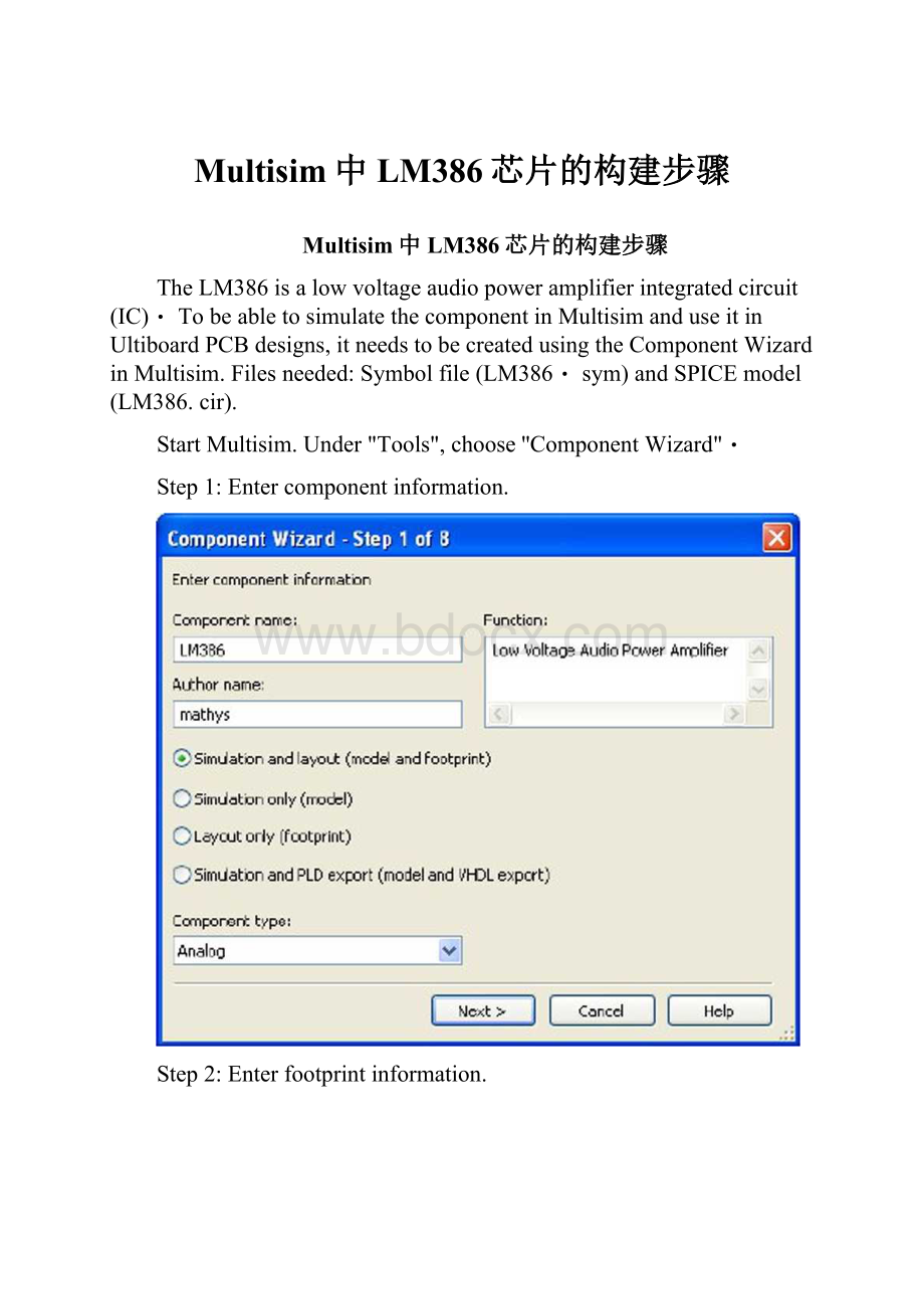
Step1:
Entercomponentinformation.
Step2:
Enterfootprintinformation.
Clickon"Selectafootprint".
Therearesome5000footprintsintheMasterDatabase・Tofindtheonethatweneedmoreeasily,clickon"Filter〃・Clickon"Addrow"andselect"Footprint"fromthedropdownmenuunder"Column"・Setthe"Operator"to"Contains"andenter"DIP8"under"Value"asshownbelow.
Selectthez,UltiboardDIPS'"footprint.
Clickon"Select"・Inthefootprintinformationwindowsetthe
numberofpinsto8.
Step3:
Entersymbolinformation.
ComponentWizard-Step3of8
Symbolset
®AN5I
Odidi
Entersymbolinformation
1Edit
Copy
Codyto…J
VBxkJ|Ncp;t7|]CodT][Help
Clickon"Edit"toopentheSymbolEditor.
ogj-B*a§?
*口\0。
疋言)riA厨炉
HNMM0应底UMUKLKshYy二二二^-IA4A14S6?
8
>r>tM
SR机如协
CmwIWi
Cpjiyik*
Cw»y*
ReWr
饰A
F
叶
1Msi6 DownloadthefileLM386・symandrememberthelocationwhereyouputit.IntheSymbolEditorclickon"File"and"Open.・・"andopenthe LM386.symfile. 曲fta td MH hY应巾Ort-*UKM3YUKFa'Z7LfttH豪YUrHm—业” 的-*UrF«常、-*Lfl-M Sr机Cun杯M加 Ca«y加SrECm»枷皿如 )'♦xZ'【啊* : o并丫•: 弧七彩込绅 thebottom Donotchangeanyofthepininformationthatappearsofthesymboleditor・Clickon"Exit"andanswer"Yes"tothe"Savechanges? "question.Nowthesymbolinformationwindowshouldlooklikethis: Entersymbolinformation Symbolset ®AN5I Odicj IEdit CopyfromDB fCopYto...| VBxkJ|Next7|]ConT][Help Step4: Setpinparameters・Clickon"\ext"andchangethepin Typesforthedifferentpins(from"BIDIRECTIONAL")tothevaluesshownbelow. Step5: Setmappinginformationbetweensymbolandlayoutfootprint. Click"Next"andfillinthefootprintpinsinasshownnext. Step6: SelectSimulationmode1.Click"\ext"toobtainthe"Selectsimulationmodel"window. DownloadthefileLM386・cirandrememberthelocationwhereyouputit.Thenclickon"Loadfromfile"andopentheLM386・cirfile・YoushouldseeawindowwiththeLM386SPICEmodelfilledinasshownbelow. q1 gnd inn 10011 ddpnr rl inn gnd 50k 口2 gnd inn 10012 ddpnp r2 inp gnd 50k 5etectsimdatonmodel SelectfromDB Copyto.・・ Modelname: LM386 Loadfromfife Modelmaker Modeldata; *CONNECTIONS: Goin1 8 *differentialinputstage,gain—setting *resistor®zandintexna.1ieedback3? esistor: Next> Corucd[Help| Step7: Mappinginformationbetweensymbolandsimulationmode1. Click"Next"andfillintheModelnodesinthePinmappingtableasfollows・(Note: Themodelnodesarenumbered1,2,3,・・・fromlefttorightinthe・SUBCKTspecification,irrespectiveofthepinnumbersinthefootprintmapping・) 5etm^DDiroinforrratbnbetv^eeisymbdandsimulationmcdd(Thes/rrbolmustcontanatfeastasmsypinsasthemodelhasconnecticnpoints.) Pinmoppingtcbb; Symbdpns Modelnodes Vs 6 Gan] 1 Gein8 8 VOJt-IN 5 2 十IN 3 Grd 4 Bypass 7 二叵冈 Faml/tree: Sojrce? UserCdcbwc CMOS TTL i-i Anabo ,w8版 咄Oodcs Oditj Step8: Savecomponenttodatabase・ClickNextandinthenextwindowclickon"UserDatabase''andselect,zAnalog"・ 乐ComponentWizard-Step8ofB A^enradj^ncherals “X]Iw[On: ®|] Clickon"Addfamily"andenter"Amplifier"forthefamilyname. Finally,click"Finish"andyouaredonewithLM386componentcreation.CheckthatyoucanselectthecomponentinMultisim. Thenplacethecomponentonaschematic. g)6f紳Eg少"林I«fc”gg-別』0j 可R&Q®口PEBS=®E・I3;: : “•・三込兰二*>? E2l ▼: K28<0初[人J»“■•.•'台三[ 兰空l^x【勺兰聖 赴咧】・厂 11L1 mw*7如,;is加彩曲申


- 配套讲稿:
如PPT文件的首页显示word图标,表示该PPT已包含配套word讲稿。双击word图标可打开word文档。
- 特殊限制:
部分文档作品中含有的国旗、国徽等图片,仅作为作品整体效果示例展示,禁止商用。设计者仅对作品中独创性部分享有著作权。
- 关 键 词:
- Multisim LM386 芯片 构建 步骤
 冰豆网所有资源均是用户自行上传分享,仅供网友学习交流,未经上传用户书面授权,请勿作他用。
 #2机组现场施工用电布置措施.docx
-
《个人贵金属质押借款合同》兴业银行.docx
-
《科学发展观和小康社会的经济建设》复习导学案.docx
-
《我和祖父的园子》第一课时教案两篇word.docx
-
《质量》教学案例与设计.docx
-
2惠农小册子.docx
-
7A版个人与团队模拟考试题及答案.docx
-
10篇新部编四年级下册语文课内外阅读理解专项练习题及答案.docx
-
16初四物理热和能知识点总结精讲.docx
-
20XX社会语言经典语录流行风暴.docx
-
48篇教学案例分析报告题.docx
-
《电子工厂安全管理制度汇总》.docx
-
《机械制造课程设计》指导.docx
-
《钱学森》教案第二课时.docx
-
《边城》读后感5篇.docx
-
《固定式压力容器安全技术监察规程》.docx
-
《论雷峰塔的倒掉》.docx
-
《手术台就是阵地》教学设计三年级语文下册.docx
-
《夏洛的网》课外阅读教学设计.docx
-
《自己的花是让别人看的》教案.docx
-
3C检查表090429.docx
-
7客运专线CRTSⅡ型板式无砟轨道施工工法.docx
-
《笔算除法》课时教案设计.docx
-
11#楼高大模板支撑体系专项方案.docx
-
17科学分析经济形势.docx
-
《电流和电路》易错题精讲综合检测题与答案.docx
-
《会计信息系统》习题含答案.docx
-
《汽车电器设备与维修》发电机分教考分离试题及标准答案.docx
-
《四川省排污许可证管理暂行办法》.docx
-
《新编实用英语》教案第一册Unit.docx
-
0母版锅炉值班员计算题WORD版.docx
-
3年级下册英语单词记忆人教版.docx
-
数字万年历设计与实现设计大学论文.docx
-
精品公园生态环境保护项目研究建议书正文.docx
-
水利三类人员安全员b证考试题库及答案完整版.docx
-
精品西师版小学六年级上册语文教案2.docx
-
司法局综合业务用房建设项目可研报告.docx
-
四川省居民消费结构的计量经济学分析.docx
-
精选部编版九上语文课外古诗词背景注释译文赏析.docx
-
四年级上学期生命教育教案设计54459.docx
-
精选医学指甲观察人体疾病doc.docx
-
四年级英语下册136课教案人教新版.docx
-
九年级化学资料一二.docx
-
苏教版三年级数学下册小数的初步认识练习题精选63.docx
-
救援环境下生存常识汇总.docx
-
苏少版五年级下册音乐第五课《凤阳花鼓》教案.docx
-
太原市高三期末 英语.docx
-
康平县小城子镇清武粮食收购站建设项目.docx
-
特岗教师《教育理论综合》复习题集第365篇.docx
-
可贵的沉默讲课比赛材料.docx
-
天津市河东区届中考一模英语试题扫描版.docx
