 EDA设计基本电路.docx
- 文档编号:26270183
- 上传时间:2023-06-17
- 格式:DOCX
- 页数:25
- 大小:99.42KB
EDA设计基本电路.docx
《EDA设计基本电路.docx》由会员分享,可在线阅读,更多相关《EDA设计基本电路.docx(25页珍藏版)》请在冰豆网上搜索。
EDA设计基本电路
基本时序电路
实例2-1对触发器及时钟信号的VHDL描述
一、设计任务:
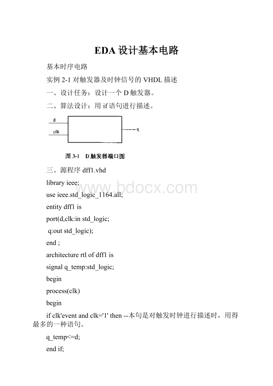
设计一个D触发器。
二、算法设计:
用if语句进行描述。
三、源程序dff1.vhd
libraryieee;
useieee.std_logic_1164.all;
entitydff1is
port(d,clk:
instd_logic;
q:
outstd_logic);
end;
architecturertlofdff1is
signalq_temp:
std_logic;
begin
process(clk)
begin
ifclk'eventandclk='1'then--本句是对触发时钟进行描述时,用得最多的一种语句。
q_temp<=d;
endif;
q<=q_temp;
endprocess;
endrtl;
--if语句中,用信号属性even来判断时钟触发事件是否发生,用clk='1'规定触发时钟的上沿为有效触发沿。
语句“ifclk'eventandclk='1'then”的含义是:
若有触发时钟信号产生且当触发时钟的上沿出现时,容许触发器读入输入数据。
如果上述事件没有发生,则不容许触发器读入输入数据,而读入输入数据的规则由后续语句规定。
--若规定触发器是下沿触发,则触发时钟描述语句为“ifclk'eventandclk='0'then”。
--图3—2是D触发器的仿真波形图。
由图可以看出,触发器的默认开机状态值为'0',在第一个触发脉冲的上沿出现时刻,电路系统把数据'1'写入触发器。
在第二个触发脉冲的上沿出现时刻,电路系统仍把数据'1'写入触发器,但由于触发器原状态为'1',写入数据仍为'1',所以触发器保持'1'状态不变。
在第三个触发脉冲的上沿出现时刻,输入数据变为'0',电路系统把数据'0'写入触发器。
以后尽管有触发脉冲的上沿出现,但是输入值为'0'不变,所以触发器保持'0'状态。
图3-2D触发器的仿真波形图
实例2-2锁存器
一、设计任务:
设计一个锁存器。
二、算法设计:
用条件涵盖不完整的if语句实现锁存器。
三、源程序latch.vhd
libraryieee;
useieee.std_logic_1164.all;
entitylatchis
port(kz,din:
instd_logic;
q:
outstd_logic);
end;
architectureaoflatchis
signalq_temp:
std_logic;
begin
p1:
process(kz,din)
begin
ifkz='1'then
q_temp<=din;
endif;
q<=q_temp;
endprocess;
end;
四、源程序说明
1.用条件涵盖不完整的if语句可以实现锁存器。
这个结果提示我们在用if条件语句进行设计时,要明确设计的任务是什么,若设计的不是锁存器,则必须使条件涵盖完整,以避免错误引入锁存器。
2.若本例描述的锁存器中的控制信号kz是一个异步信号,而且输入信号较高,就有可能在输出形成冒险干扰,应注意克服。
3.图3-11是锁存器正常工作时的仿真波形图。
实例2-3串入串出移存器
一、设计任务:
设计一个4位串入串出移存器。
二、算法设计:
用if语句及数组赋值语句描述4位串入串出移存器。
三、源程序shift4.vhd
libraryieee;
useieee.std_logic_1164.all;
entityshift4is
port(clk,din:
instd_logic;
fo:
outstd_logic);
end;
architectureaofshift4is
signald:
std_logic_vector(4downto0);
begin
process(clk)
begin
if(clk'eventandclk='1')then
d(0)<=din;
d(4downto1)<=d(3downto0);
fo<=d(4);
endif;
endprocess;
end;
四、时序仿真结果
实例2-4串入串出双向移存器
一、设计任务:
设计一个4位串入串出双向移存器。
二、算法设计:
用if语句及循环语句描述4位串入串出双向移存器。
三、源程序:
shift4_4.vhd
libraryieee;
useieee.std_logic_1164.all;
entityshift4_4is
port(dr,dl,clk:
instd_logic;
kz:
inbit;
fr,fl:
outstd_logic);
end;
architectureaofshift4_4is
signalq:
std_logic_vector(3downto0);
begin
process(clk)
begin
if(clk'eventandclk='1')then
ifkz='1'then--kz='1'时,移存器执行右移功能,右移输入信号是dr。
q(0)<=dr;
loop1:
foriin0to2loop
q(i+1)<=q(i);
endloop;
else--kz='0'时,移存器执行左移功能,左移输入信号是dl。
q(3)<=dl;
loop2:
foriin1to3loop
q(i-1)<=q(i);
endloop;
endif;
endif;
fr<=q(3);
fl<=q(0);
endprocess;
end;
实例2-5串入并出移存器
一、设计任务设计一个5位串入并出移存器。
二、算法设计用if语句描述5位串入并出移存器。
三、源程序
libraryieee;
useieee.std_logic_1164.all;
entityshift4_5is
port(shift,cr,clk:
instd_logic;
y:
outstd_logic_vector(4downto0));
end;
architectureaofshift4_5is
signaltemp_date:
std_logic_vector(5downto0);
begin
process(clk)
begin
if(clk'eventandclk='1')then
ifcr='0'then
temp_date<=(others=>'0');--表示各位均赋0。
elsiftemp_date(0)='0'then
temp_date<=shift&"01111";
else
temp_date<=shift&temp_date(5downto1);
endif;
endif;
endprocess;
process
begin
iftemp_date(0)='0'then
y<=temp_date(5downto1);
else
y<="00000";
endif;
endprocess;
end;
实例2-6并入串出移存器
一、设计任务设计一个4位并入串出移存器。
二、算法设计用if语句描述4位并入串出移存器。
三、源程序
libraryieee;
useieee.std_logic_1164.all;
useieee.std_logic_unsigned.all;
entityshift4_6is
port(cr,clk:
instd_logic;
shift:
instd_logic_vector(3downto0);
y:
outstd_logic);
end;
architectureaofshift4_6is
signalk:
std_logic_vector(3downto0);
signalq:
std_logic_vector(1downto0);
begin
p1:
process(clk)
begin
if(clk'eventandclk='1')then
q<=q+1;
endif;
endprocess;
p2:
process(clk)
begin
ifcr='0'then
--在cr='0'条件下,若无操作规定,则K维持初始值"0000"。
elsif(clk'eventandclk='1')then
ifq>"00"then
k(3downto1)<=k(2downto0);
elsifq="00"then
k<=shift;
endif;
endif;
y<=k(3);
endprocess;
end;
实例2-7一热态位编码计数器
一、设计任务:
设计一个一热态位(one-hot)编码的四进计数器。
该计数器类型也可称为“循环出1(或0)计数器”或“循环计数器”。
其特点是对每一个计数状态采用一个触发器。
二、算法设计用if语句描述一热态位编码四进计数器。
三、源程序hot_count.vhd
libraryieee;
useieee.std_logic_1164.all;
entityhot_countis
port(clk:
instd_logic;
y:
outstd_logic_vector(3downto0));
end;
architectureshift_1ofhot_countis
signalq:
std_logic_vector(3downto0);
begin
process(clk)
begin
if(clk'eventandclk='1')then
if(q="1000"orq="0100"orq="0010"orq="0001")then
q<=q(0)&q(3)&q
(2)&q
(1);
else
q<="1000";
endif;
endif;
endprocess;
y<=q;
end;
--本电路具有自启动功能。
一旦电路进入非法状态之后,电路会自动恢复合法状态。
--由仿真波形可以看出,开机时电路进入“0000”非法状态,之后电路会自动跳出该非法状态而恢复合法状态“1000”。
四、时序仿真结果:
实例2-8二进制(M=16)计数器
一、设计任务:
设计一个二进制(M=16)计数器。
一般把计数器的模值M=2n、状态编码为自然二进制数的计数器简称为二进制计数器。
二、算法设计:
用if语句描述二进制(M=16)计数器。
三、源程序count16.vhd
libraryieee;
useieee.std_logic_1164.all;
useieee.std_logic_unsigned.all;
entitycount16is
port(clk:
inbit;
oc:
outbit;
y:
outintegerrange0to15);
end;
architectureaofcount16is
signalq:
integerrange0to15;
begin
process(clk)
begin
if(clk'eventandclk='1')then
q<=q+1;
endif;
ifq=15then
oc<='0';
else
oc<='1';
endif;
y<=q;
endprocess;
end;
--程序中oc是计数器进位输出端。
用整数数据类型设计二进制计数器是很方便的。
若要M=256,只要把整数数据范围改为:
integerrange0to255。
实例2-9BCD码60进同步计数器
一、设计任务:
设计一个BCD码60进同步计数器。
个位显示0~9,十位显示0~5,均用4位二进制数表示。
二、算法设计:
个位计数器的模M=10,十位计数器的模M=6。
用if语句描述该计数器。
三、源程序count6_10tb.vhd
libraryieee;
useieee.std_logic_1164.all;
useieee.std_logic_unsigned.all;
entitycount6_10tbis
port(clk,clr:
instd_logic;
oc:
outstd_logic;
y0,y1:
outstd_logic_vector(3downto0));
end;
architectureaofcount6_10tbis
signalq:
std_logic_vector(3downto0);
signalk:
std_logic_vector(3downto0);
signalj9,j60:
std_logic;
begin
p1:
process(clk)
begin
ifclr='0'then
q<="0000";--清零。
elsif(clk'eventandclk='1')then
ifq="1001"then
q<="0000";
else
q<=q+1;
endif;
endif;
y0<=q;
endprocess;
p2:
process(clk)
begin
ifclr='0'then
k<="0000";--清零。
elsif(clk'eventandclk='1')then
ifq="1001"then
ifk="0101"then
k<="0000";
else
k<=k+1;
endif;
else
k<=k;
endif;
endif;
y1<=k;
ifq="1001"andk="0101"then
j60<='0';
else
j60<='1';
endif;
oc<=j60;
endprocess;
end;
--两级计数器的模M=M1*M0。
本程序描述的计数器是一个同步计数器,由于十位计数器和个位计数器使用同一个时钟,所以程序中使用q=”1001”条件对十位计数器的时钟作用时刻进行控制。
四、仿真结果
常用组合电路设计
实例13线-8线译码器
一、设计任务:
描述一个3线-8线译码器,使能端为g1、g2a、g2b,地址选择端为a、b、c,输出端为总线y。
二、算法设计:
用case语句描述电路,利用真值表辅助,很容易编写出程序。
三、端口图:
四、实验原程序:
decoder3_8.vhd
libraryieee;
useieee.std_logic_1164.all;--库函数声名
entitydecoder3_8is
port(a,b,c,g1,g2a,g2b:
instd_logic;
y:
outstd_logic_vector(7downto0));
end;--实体即输入输出端口定义
architecturertlofdecoder3_8is--结构体描述
signaldz:
std_logic_vector(2downto0);
begin
dz<=c&b&a;
process(dz,g1,g2a,g2b)
begin
if(g1='1'andg2a='0'andg2b='0')then
casedzis
when"000"=>y<="11111110";
when"001"=>y<="11111101";
when"010"=>y<="11111011";
when"011"=>y<="11110111";
when"100"=>y<="11101111";
when"101"=>y<="11011111";
when"110"=>y<="10111111";
when"111"=>y<="01111111";
whenothers=>y<="XXXXXXXX";
endcase;
else
y<="11111111";
endif;
endprocess;
end;
五、时序仿真结果图:
--程序描述的3-8线译码器与中小规模集成电路74LS138功能相同。
实例2优先编码器
一、设计任务:
描述一个优先编码器。
该电路有8个输入端d(8位),3个输出端y(3位)。
二、算法设计:
用if语句描述电路,利用真值表辅助,编写出程序。
三、端口图:
四、真值表
真值表
d7
d6
d5
d4
d3
d2
d1
d0
y2
y1
y0
0
x
x
x
x
x
x
x
0
0
0
1
0
x
x
x
x
x
x
0
0
1
1
1
0
x
x
x
x
x
0
1
0
1
1
1
0
x
x
x
x
0
1
1
1
1
1
1
0
x
x
1
0
0
1
1
1
1
1
0
x
x
1
0
1
1
1
1
1
1
1
0
x
1
1
0
1
1
1
1
1
1
1
0
1
1
1
五、实验源程序encoder.vhd
libraryieee;
useieee.std_logic_1164.all;
entityencoderis
port(d:
instd_logic_vector(0to7);
y:
outstd_logic_vector(0to2));
end;
architectureaofencoderis
begin
process
begin
ifd(7)='0'theny<="000";
elsifd(6)='0'theny<="001";
elsifd(5)='0'theny<="010";
elsifd(4)='0'theny<="011";
elsifd(3)='0'theny<="100";
elsifd
(2)='0'theny<="101";
elsifd
(1)='0'theny<="110";
elsifd(0)='0'theny<="111";
endif;
endprocess;
end;
--由优先编码器的真值表可知,输入信号d7的优先权最高,只要d7=0,无论其他为何值,输出都由d7决定。
--vhdl语言可用if语句描述优先权特性,在if语句中最先描述d7这个优先编码条件。
优先级别越低,在语句中描述的顺序越靠后。
实例3二-十进制BCD译码器
一、设计任务:
设计一个二-十进制BCD译码器。
译码器输入din为4位二进制数,输出为以4位二进制数表示的两个十进制数a、b。
二、算法设计:
用行为描述模式描述译码器。
三、源程序v2_10bcdymq.vhd
libraryieee;
useieee.std_logic_1164.all;
useieee.std_logic_signed.all;
entityv2_10bcdymqis
port(din:
inintegerrange15downto0;
a,b:
outintegerrange9downto0);
end;
--integer为整数数据类型,要使用关键字integerrange(数值范围)。
architectureaofv2_10bcdymqis
begin
p1:
process
begin
ifdin<10then
a<=din;
b<=0;
else
a<=din-10;
b<=1;
endif;
endprocessp1;
end;
实例4四选一数据选择器
一、设计任务:
描述一个四选一数据选择器电路,令a、b、c、d为输入信号,e1,e2为选择信号,fout为输出信号。
二、算法设计用case语句描述。
在VHDL语言中描述一个2选一的多路选择器的方法有多种,例如:
在一个进程中使if-when-else语句;在一个进程中使用case语句;使用withselect构造或使用结构VHDL。
推荐的使用方法是使用whenelse构造,这样在VHDL代码中只用1行就可以描述2选1多路选择器。
例如:
LIBRARYIEEE;
USEIEEE.STD_LOGIC_1164.ALL;
ENTITYMUX2IS
PORT(A,B,SEL:
INSTD_LOGIC;
Q:
OUTSTD_LOGIC);
END;
ARCHITECTUREAOFMUX2IS
BEGIN
Q<=AWHENSEL=’0’ELSEB;
END;
三、实验源程序一mux4.vhd-用when-else语句
libraryieee;
useieee.std_logic_1164.all;
entitymux4is
port(a,b,c,d,e1,e2:
inbit;
fout:
outbit);
endmux4;
--e1,e2为选择信号,当e1e2="00",a输出;当e1e2="01",b输出;当e1e2="10",c输出,--当e1e2="11",d输出。
architectureaofmux4is
begin
fout<=aWHENe1&e2="00"ELSE--&并置符,不是逻辑运算符
bWHENe1&e2="01"ELSE
cWHENe1&e2="10"ELSE
dWHENe1&e2="11"ELSE
'0';
enda;
也可用以下程序仿真:
libraryieee;
useieee.std_logic_1164.all;
entitymux4is
port(a,b,c,d,e1,e2:
instd_logic;
fout:
outstd_logic);
endmux4;
architectureaofmux4is
signals:
std_logic_vector(1downto0);
begin
s<=e1&e2;
fout<=aWHENs="00"ELSE
bWHENs="01"ELSE
cWHENs="10"ELSE
dWHENs="11"ELSE
'0


- 配套讲稿:
如PPT文件的首页显示word图标,表示该PPT已包含配套word讲稿。双击word图标可打开word文档。
- 特殊限制:
部分文档作品中含有的国旗、国徽等图片,仅作为作品整体效果示例展示,禁止商用。设计者仅对作品中独创性部分享有著作权。
- 关 键 词:
- EDA 设计 基本 电路
 冰豆网所有资源均是用户自行上传分享,仅供网友学习交流,未经上传用户书面授权,请勿作他用。
 《爱和自由》读书心得15篇.docx
-
《极致服务》读后感.docx
-
《上海市饮用水水源保护条例》.docx
-
《变化社会中的政治秩序》读后感.docx
-
《吵闹村的孩子》读后感15篇.docx
-
《摆渡人》读后感受1000字左右范文.docx
-
《国际贸易学》题库南京大学.docx
-
《诚信备考》主题班会活动.docx
-
《高等学校教师职业道德修养》考试要点演示教学.docx
-
《巴菲特的护城河》精华摘要.docx
-
《繁星春水》读后感14篇.docx
-
#电控发动机的故障诊断与排除.docx
-
《归去来兮辞》优化教案及课文解析.docx
-
《办公室秘书个人党性分析材料》.docx
-
《会飞的气球》大班教案.docx
-
#生命生活与安全5上.docx
-
《城南旧事》的读后感作文范文10篇.docx
-
《标志用公共信息图形符号 第1部分通用符号》GBT 100011.docx
-
《初级会计实务》考试试题及答案解析.docx
-
《公共基础知识》考点《公文写作与处理》.docx
-
《海底世界》大班教案.docx
-
#ds18b20可调温度控制器.docx
-
《爱的教育》读书笔记范文10篇.docx
-
《公路养护工程量清单及计量规范》编制.docx
-
《建设工程监理规范》新旧版本区别.docx
-
《生活补助申请报告》.docx
-
《纸质档案管理规范》word版.docx
-
00种英语游戏.docx
-
09多元实用才能2.docx
-
《财经法规与会计职业道德》全真模拟试题及参考答案四.docx
-
14秋学前教育教育理论期中考试试题.docx
-
《大数据导论》19秋期末考核0001.docx
-
东岗学校2017年精神文明建设工作计划Word文件下载.doc
-
重庆机床厂Word格式文档下载.docx
-
入党申请书文档格式.docx
-
人教版五年级数学下册通分专项练习题120Word下载.docx
-
东洛中心小学优秀教师评选方案Word格式文档下载.doc
-
施工组织与管理教案文档格式.docx
-
三角形的相似复习教案Word格式文档下载.docx
-
东炉小学教师绩效工资分配方案草案Word文档格式.doc
-
商品房买卖合同补充协议Word下载.docx
-
特高压三华题库Word下载.docx
-
省级优秀学生典型事迹材料Word格式文档下载.docx
-
毕业设计创作整套表格有批注的汇编Word格式文档下载.docx
-
初一简短评语大全Word文档格式.docx
-
小编带你逛逛深圳电子批发市场:都会电子商城文档格式.doc
-
二级建设工程法规及相关知识模拟题及答案解析100Word文件下载.docx
-
试论我国网上银行的立法完善学位论文Word文档下载推荐.docx
-
财务知识政治经济学案例分析最全版Word下载.docx
-
最新文化局领导讲话材料Word文档下载推荐.docx
-
绵阳市小学毕业小升初模拟数学试题共6套附详细答案Word文档下载推荐.docx
