 packettracer510全攻略下Word下载.docx
- 文档编号:22263203
- 上传时间:2023-02-03
- 格式:DOCX
- 页数:32
- 大小:2.07MB
packettracer510全攻略下Word下载.docx
《packettracer510全攻略下Word下载.docx》由会员分享,可在线阅读,更多相关《packettracer510全攻略下Word下载.docx(32页珍藏版)》请在冰豆网上搜索。
图七?
Router4的OSPF配置
图八 查看路由器中的路由表
3、校验、诊断
图九 showipprotocol查看路由器中所启用的路由计算协议
图十 showipospf
图十一 showipospfinterface
图十二
图十三 showipospfneighbor 想看邻居
图十四 showipospfdatabase
图十五 debugipospfevents开启诊断,nodebugipospfevents关闭诊断
图十六 pc2ping通所有网段内的计算机或路由器
在这里只能进行最为简单的OSPF配置了,可以完成CCNA的实验。
十一、路由器实现Vlan间通信
一、实验拓扑图
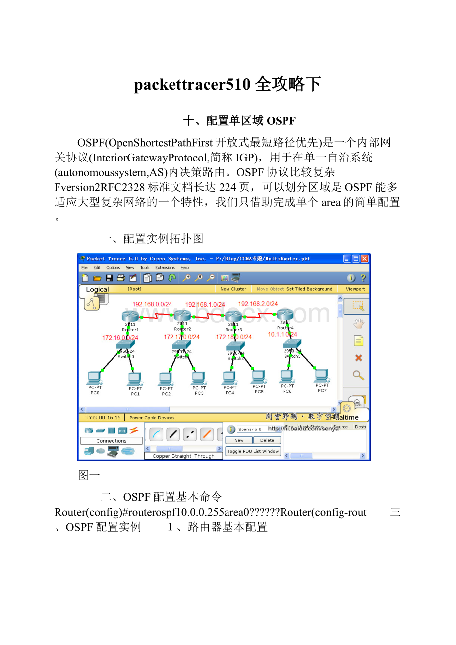
图一 路由器:
Cisco2811,交换机:
Cisco2950
二、创建Vlan 2950#vlandatabae 2950(vlan)#vlan10namemath 2950(vlan)#vlan20namechinese
图二
三、把交换机端口分配给Vlan 2950#conft 2950(config)#intrangefa0/2-3 2950(config-if-range)#switchportmodeaccess 2950(config-if-range)#switchportaccessvlan10 2950(config-if-range)#intrangefa0/4-5 2950(config-if-range)#switchportmodeaccess 2950(config-if-range)#switchportaccessvlan20
四、配置交换机trunk端口 2950(config)intfa0/1 2950(config-if)switchportmodetrunk
图四
五、配置路由器子接口 Router#conft Router(config)#intfa0/1.1 Router(config-subif)#encapsulationdot1q10 Router(config-subif)#intfa0/1.2 Router(config-subif)#encapsulationdot1q20 Router(config-subif)#intfa0/1 Router(config-if)#noshut
图五
图六 查看路由器中的路由表
六、配置计算机,测试
图七 不同网段中的计算机完全可以ping通
十二、PPP
PPP(PointtoPointProtocol)数据链路层协议。
两种认证方式:
一种是PAP,一种是CHAP。
相对来说PAP的认证方式安全性没有CHAP高。
PAP在传输password是明文的,而CHAP在传输过程中不传输密码,PAP认证是通过两次握手实现的,而CHAP则是通过3次握手实现的。
一、实验配置拓扑图
二、PPP的基本配置命令 Router(config-if)#encapsulationPPP Router(config-if)#PPPmultilink Router(config-if)#PPPauthenticationchap
三、配置PPP
图二 路由器Boson上配置PPP的命令
图三?
Newyork上配置PPP的命令
图四 启用RIP路由协议,两个路由器要配置RIP
Boson路由器的配置:
Boston#shrunning-configBuildingconfiguration...
Currentconfiguration:
652bytes!
version12.4noservicepassword-encryption!
hostnameBoston!
!
usernameNewyorkpassword0senya!
ipsshversion1noipdomain-lookup!
interfaceFastEthernet0/0noipaddressduplexautospeedautoshutdown!
interfaceFastEthernet0/1duplexautospeedauto!
interfaceSerial0/3/0descriptionLinktoRouterNewyorkencapsulationppppppauthenticationchapclockrate56000!
interfaceVlan1noipaddressshutdown!
routerripversion2!
ipclassless!
linecon0linevty04login!
end
Newyork路由器的配置:
Newyork#shrunning-configBuildingconfiguration...
606bytes!
hostnameNewyork!
usernameBostonpassword0senya!
ipsshversion1!
interfaceSerial0/3/0descriptionlinktoBostonencapsulationppppppauthenticationchap!
图五 配置计算机的IP地址及网关
图六 在计算机PC0上使用ping命令检查网络的连通性
十三、帧中继FrameRelay
帧中继是一种用于连接计算机系统的面向分组的通信方法。
它主要用在公共或专用网上的局域网互联以及广域网连接。
大多数公共电信局都提供帧中继服务,把它作为建立高性能的虚拟广域连接的一种途径。
帧中继是进入带宽范围从56Kbps到1.544Mbps的广域分组交换网的用户接口。
帧中继是从综合业务数字网中发展起来的,并在1984年推荐为国际电话电报咨询委员会(CCITT)的一项标准,另外,由美国国家标准协会授权的美国TIS标准委员会也对帧中继做了一些初步工作。
数据链路连接标识符(DLCI)这个信息包含标识号,它标识多路复用到通道的逻辑连结。
帧中继交换机将两端的DLCI关联起来,它是帧中继帧格式中地字段的一个重要部分之一,这是个6位标识,表示正在进行的客户和服务器之间的连接,用于RFCOMM层。
帧中继使用DLCI来标识DTE和服务商交换机之间的虚电路。
DLCI字段的长度一般为10bit,但也可扩展为16bit,前者用二字节地址字段,后者是三字节地址字段。
23bit用四字节地址字段。
DLCI值用于标识永久虚电路(PVC),呼叫控制或管理信息。
DLCI只具有本地意义。
一、使用PacketTracer5.0构建帧中继仿真 添加三个2811路由器和一个云
图二 给2811添加一个具有串口的模块
图四 把路由器2811的串口与云的串口相连,路由器的串口为DTE
图五 实验拓扑图及IP地址、DLCI分配
二、配置FrameRelay以Router2为例,其它两个路由器相似,\\后是人为添加的注释,在实际配置时不存在Router>
en \\进入特权配置模式Router#conft \\进入全局配置模式Enterconfigurationcommands,oneperline.EndwithCNTL/Z.Router(config)#noipdomain-lookup \\取消名称解析Router(config)#hostnameRouter2 \\配置路由器的名字Router2(config)#intfa0/1 \\进入接口配置模式Router2(config-if)#noshut \\激活端口
%LINK-5-CHANGED:
InterfaceFastEthernet0/1,changedstatetoup%LINEPROTO-5-UPDOWN:
LineprotocolonInterfaceFastEthernet0/1,changedstatetoupRouter2(config-if)#intserial0/3/0Router2(config-if)#encapsulationframe-relay \\对串口serial0/3/0进行frame-relay封装Router2(config-if)#noshut
InterfaceSerial0/3/0,changedstatetoupRouter2(config-if)#%LINEPROTO-5-UPDOWN:
LineprotocolonInterfaceSerial0/3/0,changedstatetoupRouter2(config-if)#interfaceserial0/3/0.1point-to-point \\进入串口的子接口配置模式
InterfaceSerial0/3/0.1,changedstatetoup%LINEPROTO-5-UPDOWN:
LineprotocolonInterfaceSerial0/3/0.1,changedstatetoupRouter2
Router2(config-subif)#descriptionLinkRouter1DLCI30 \\为子接口添加描述Router2(config-subif)#frame-relayinterface-dlci40 \\配置DLCIRouter2(config-subif)#interfaceserial0/3/0.2point-to-point
InterfaceSerial0/3/0.2,changedstatetoup%LINEPROTO-5-UPDOWN:
LineprotocolonInterfaceSerial0/3/0.2,changedstatetoupRouter2
Router2(config-subif)#descriptionlinktoRouter0DLCI20Router2(config-subif)#frame-relayinterface-dlci41Router2(config-subif)#end%SYS-5-CONFIG_I:
ConfiguredfromconsolebyconsoleRouter2#conftEnterconfigurationcommands,oneperline.EndwithCNTL/Z.Router2(config)#routereigrp100 \\在路由器上启用EIGRP路由协议Router2(config-router)#%SYS-5-CONFIG_I:
ConfiguredfromconsolebyconsoleRouter2#copyrunning-configstartup-config \\保存配置Destinationfilename[startup-config]?
Buildingconfiguration...[OK]Router2#
路由器Router0的配置:
Router0#shrunning-configBuildingconfiguration...
830bytes!
hostnameRouter0!
interfaceSerial0/3/0noipaddressencapsulationframe-relay!
interfaceSerial0/3/0.1point-to-pointdescriptionLinktoRouter2frame-relayinterface-dlci20!
interfaceSerial0/3/0.2point-to-pointdescriptionLinktoRouter1frame-relayinterface-dlci21!
routereigrp100auto-summary!
end路由器Router1的配置Router1#shrunning-configBuildingconfiguration...
843bytes!
hostnameRouter1!
interfaceSerial0/3/0.1point-to-pointdescriptionlinktoRouter2DLCI40frame-relayinterface-dlci30!
interfaceSerial0/3/0.2point-to-pointdescriptionlinktorouter0DLCI21frame-relayinterface-dlci31!
路由器Router2的配置
Router2#shrunning-configBuildingconfiguration...
841bytes!
hostnameRouter2!
interfaceSerial0/3/0.1point-to-pointdescriptionLinkRouter1DLCI30frame-relayinterface-dlci40!
interfaceSerial0/3/0.2point-to-pointdescriptionlinktoRouter0DLCI20frame-relayinterface-dlci41!
路由器配置完毕后,还需要配置Cloud0。
图六 根据路由器的相关配置,给Cloud0的serial0配置DLCI及LMI类型
图七 根据路由器的相关配置,给Cloud0的serial1配置DLCI及LMI类型
图八 根据路由器的相关配置,给Cloud0的serial2配置DLCI及LMI类型
图九 根据路由器的相关配置,配置Cloud0的FrameRelay
三、配置各个计算机,并使用ping命令校验网络的连通性
pc0
PC>
ipconfig
th32bytesofdata:
Ping?
Packets:
Sent=4,Received=4,Lost=0(0%loss),Approximateroundtriptimesinmilli-seconds:
Minimum=110ms,Maximum=143ms,Average=126ms
Minimum=47ms,Maximum=63ms,Average=58ms
Minimum=93ms,Maximum=125ms,Average=105ms
Minimum=110ms,Maximum=123ms,Average=113ms
TL=254
Minimum=109ms,Maximum=140ms,Average=121ms
十四、PAT(基于端口的NAT)
网络地址转换(NAT,NetworkAddressTranslation)被广泛应用于各种类型Internet接入方式和备种类型的网络中。
原因很简单,NAT不仅完美地解决了lP地址不足的问题,而且还能够有效地避免来自网络外部的攻击,隐藏并保护网络内部的计算机。
NAT的实现方式有三种,即静态转换StaticNat、动态转换DynamicNat和端口多路复用OverLoad。
端口多路复用是指改变外出数据包的源端口并进行端口转换,即端口地址转换(PAT,PortAddressTranslation).采用端口多路复用方式。
内部网络的所有主机均可共享一个合法外部IP地址实现对Internet的访问,从而可以最大限度地节约IP地址资源。
同时,又可隐藏网络内部的所有主机,有效避免来自internet的攻击。
因此,目前网络中应用最多的就是端口多路复用方式。
二、路由器的基本配置路由器ISP的配置ISP#shstartup-configUsing582bytes!
version12.4servicepassword-encryption!
hostnameISP!
enablesecret5$1$mERr$Q1EnFeXJ8Ibdhx2QffKaQ.!
interfaceSerial0/3/0clockrate56000!
interfaceSerial0/3/1noipaddressshutdown!
nocdprun!
路由器Company的配置Company#shstartup-configUsing643bytes!
hostnameCompany!
interfaceFastEthernet0/1ipnatinsideduplexautospeedauto!
interfaceSerial0/3/0ipnatoutside!
ipnatinsidesourcelist1interfaceSerial0/3/0overloadipclasslessiproute0.0.0!
在路由器Company上配置PAT的命令Company(config)#iproute0.0.0\\配置默认路由\\配置一个标准访问控制列表Company(config)#ipnatinsidesourcelist1interfaceSerial0/3/0overload \\启用PAT私有IP地址的来源来自于ACL1,使用serial0/3/0上的公共IP地址进行转换,overload表示使用端口号进行转换Company(config)#intfa0/1Company(config-if)#ipnatinsideCompany(config-if)#intserial0/3/0Company(config-if)#ipnatoutside
三、校验、查看PAT的配置及运行状况 测试,又在实验拓扑图中添加了一台服务器。
Company#shipnattranslationsProInsideglobal?
Insidelocal?
Outsidelocal?
Outsideglobal
Company#sh


- 配套讲稿:
如PPT文件的首页显示word图标,表示该PPT已包含配套word讲稿。双击word图标可打开word文档。
- 特殊限制:
部分文档作品中含有的国旗、国徽等图片,仅作为作品整体效果示例展示,禁止商用。设计者仅对作品中独创性部分享有著作权。
- 关 键 词:
- packettracer510 攻略
 冰豆网所有资源均是用户自行上传分享,仅供网友学习交流,未经上传用户书面授权,请勿作他用。
 广东省普通高中学业水平考试数学科考试大纲Word文档下载推荐.docx
-
计算题测试文档格式.docx
-
会计年终总结范文精选10篇Word文件下载.docx
-
基坑支护及降排水方案Word格式文档下载.docx
-
古代诗歌鉴赏一剪梅学案Word文档格式.docx
-
国标舞考级Word文件下载.docx
-
机电工程质量验收规范是什么Word文档下载推荐.docx
-
技术员工作自我评价文档格式.docx
-
交警支队车棚改造工程施工合同文档格式.docx
-
护士变更注册申请审核表与示范文本Word文档下载推荐.docx
-
最新学校新冠肺炎疫情防控应急预案Word文件下载.docx
-
GB50204钢筋规范之欧阳总创编Word格式文档下载.docx
-
《半期整改措施》Word格式.docx
-
诊断 症状学腰背痛关节痛汇总.docx
-
英美文学欣赏The Analysis of Shelleys Ode to the West Wind.docx
-
增值税营改增所得税消费税车购税测试题.docx
-
整理二级建造师管理真题.docx
-
英语三级重点高频词汇导入背单词APP使用.docx
-
浙教版学年九年级数学上册第2章测试题及答案.docx
-
证件照教学设计方案.docx
-
优品课件之《从锁国走向开国的日本》教案.docx
-
整理北京交通大学万用表组装实验报告.docx
-
质量管理计划.docx
-
有机化学鉴别.docx
-
整理照明灯饰灯具行业分类英语词汇.docx
-
濉溪县城市总体规划公示.docx
-
智能化工程质量验收记录表.docx
-
学生会纪检部工作总结.docx
-
幼儿园保教主任发言稿.docx
-
跆拳道协会工作总结.docx
-
中国茶叶店连锁市场竞争分析与竞争战略研究报告.docx
-
学宪法讲宪法主题演讲稿800字精选5篇弘扬宪法精神演讲稿5篇.docx
-
在教学中通过借鉴和学习我慢慢找到了适合的教学之路.docx
-
计算机一级电子表格.docx
-
证券发行与承销模拟64有答案.docx
-
中学信息技术教案.docx
-
EVA挣值分析举例.docx
-
人教版必修3第五单元《近代中国的思想解放潮流》word学案.docx
-
新版期间核查作业指导书.docx
-
中国天气复习题剖析.docx
-
GMP检查终总结.docx
-
人教版三年级数学上册教案第二单元.docx
-
监理工程暂停延期申请表.docx
-
造林施工组织设计.docx
-
中秋节活动主持词.docx
-
整理山西五老峰风景区导游词0.docx
-
学年湖北省武汉一中高二考英语试题Word版+听力.docx
-
建设工程工程量清单计价编制示例doc.docx
-
真叫卢俊 分享 大盘新时代.docx
-
推荐锂离子动力电池行业深度分析.docx
-
Multisim 8仿真软件应用.docx
