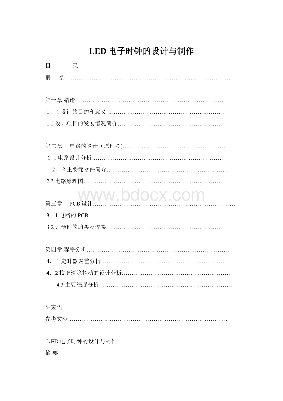
 LED电子时钟的设计与制作Word文档格式.docx
- 文档编号:13994204
- 上传时间:2022-10-16
- 格式:DOCX
- 页数:12
- 大小:118.74KB
LED电子时钟的设计与制作Word文档格式.docx
《LED电子时钟的设计与制作Word文档格式.docx》由会员分享,可在线阅读,更多相关《LED电子时钟的设计与制作Word文档格式.docx(12页珍藏版)》请在冰豆网上搜索。

1.2设计项目的发展情况简介………………………………………………
第二章 电路的设计(原理图)………………………………………………
2.1电路设计分析……………………………………………………………
2.2主要元器件简介…………………………………………………………
2.3电路原理图………………………………………………………………
第三章 PCB设计…………………………………………………………………
3.1电路的PCB…………………………………………………………………
3.2元器件的购买及焊接………………………………………………………
第四章程序分析…………………………………………………………………
4.1定时器误差分析……………………………………………………………
4.2按键消除抖动的设计分析…………………………………………………
4.3主要程序分析………………………………………………………………
结束语……………………………………………………………………………
参考文献…………………………………………………………………………
LED电子时钟的设计与制作
摘要
本次设计中的LED数码管电子时钟电路采用24小时制记时方式。
本次设计采用AT89C51单片机的扩展芯片和6个三极管做驱动,由六块LED数码管构成的显示系统,与传统的基于8/16位普通单片机的LED显示系统相比较,本系统在不显著地增加系统成本的情况下,可支持更多的LED数码管稳定显示。
设计采用AT89C51单片机,配备11.0592MHz晶振,复位电路为上电复位。
采用软件译码动态显示,考虑直接用单片机I/O口作为位选时可能驱动功率不够,可采用三极管作驱动共阳极数码管显示。
6位8段LED数码管作正常、调时和节电显示,时间按时分秒排列,时钟误差:
24小时误差3~5秒,并且在按键的作用下可以进行调时,调分,复位功能。
本电路采用直流5V电源供电,可用一般带电源线的MP3充电器稍微改造而成。
同时为了限流保护电路也用了若干个阻值不等的电阻。
在本文一开始做了一些概述主要说明此设计的目的和意义,并会对这类设计项目发展情况做个简介。
这是对这次设计很重要的一个认识是前提和设计者必须明确和了解的。
然后本文对此设计做了一些简要分析,这对理清设计思想很重要。
然后还对设计中用到的元器件进行比较全面的介绍。
如AT89C51、74HC164、LED等。
只有真正了解了元器件的特性和功能才能让这些元器件在设计中起到作用。
电子整个设计第一步是电路原理图,它直接关系着后续的工作。
接着当原理图完成好后就要为后面的刻板做准备了,这就是PCB印制电路板的制作。
它影响了整个设计的布局是能不能成功的条件。
紧接着就是程序了,如果只有硬件电路而没有程序,那么这个设计将一文不值,也就是说是一堆破铜烂铁。
所以这部分也是非常重要的。
最后结合整个设计总结了一些心得体会为这次的设计画上完满的句号。
也为以后更好的设计提供经验。
关键词:
AT89C51,LED,时钟,电路的原理图和PCB图
Abstract
Inthisdesign LEDnixietube electronclockelectric circuitselects24hour systemtimemethods.Thisdesignusesat89C51monolithicintegratedcircuittheexpansionchipand6triodesmakestheactuation,by sixLED nixie tubeconstitutiondisplaysystem,compares withthetraditionbasedon8/16 ordinary monolithic integratedcircuit LEDdisplaysystem, thissystemin not obviouslyincreasesthesystemcostinthesituation,maysupportthemore LEDnixie tubestabledemonstration.Thedesign uses at89C51monolithicintegratedcircuit,providesthe11.0592MHzcrystaloscillator,repositionstheelectric circuit foron electricity replacement.Uses thesoftwaredecodingdynamicdemonstration,considereddirectlyelectsas thepositionwhen possiblyactuatesthepowerwiththemonolithicintegratedcircuitI/O mouth tobeinsufficient, may usethetriode tomaketheactuationaltogetheranode nixie tubedemonstration.68section ofLED nixietubesmakenormal,thetimingandtheelectricitysavingdemonstrated, time ontimeminutesandsecondsarrangement,clockerror:
24 hourerroneous3~5seconds, andmaycarryonthetimingunderthepressed keyfunction,movestheminute,the replacementfunction.Thiselectriccircuitusesdirects currentthe 5Vpowersourcepower supply,the available commonbeltpowerlineMP3batterychargertransforms slightly becomes.Simultaneouslyinordertolimit flowstheprotectioncircuitalsoto usecertain resistancenumberdifferentresistance.
Madesomeoutlinesinthisarticlemainly toexplainfromtheverybeginningthis designsthegoalandthe significance,andcould makeasynopsistothis kindofdesignprojectdevelopmentsituation. Thisisthepremiseandthe designer must be clearabout to this designveryimportantunderstanding and understand.
Thenthis articledesignedregarding thishasmade somebriefanalyses,thistoclear offthedesignconcepttobeveryimportant. Thenalso todesigns theprimary devicewhichusestocarry on thequite comprehensiveintroduction.As AT89C51,74HC164,LEDand soon.Only thenhadunderstoodtrulytheprimarydevicecharacteristicandthefunctioncanlettheseprimarydevices playtherolein thedesign.Theelectron entire designsfirst stepis theelectric circuitschematicdiagram;
itisrelatingthefollowingwork directly.
Afterthenthe schematicdiagramcompletedneedstoprepare mechanicallyforbehind,thiswasthe PCBprintedcircuit boardmanufacture.Ithas affected theconditionwhichentiredesignlayoutiscansucceed
Thefollowingcloselywastheprocedure,ifonlythenthehardwareelectriccircuitdidnot havethe procedure,then thisdesign willnotbewortharedcent,inotherwords, willbeapileofscrapcopper rotteniron.Thereforethis part alsois extremelyimportant.
Finally unified the entiredesignto summarizesomeattainments torealize marked theperfect periodforthis timedesign.Andwillprovide the experienceforalaterbetter design.
Keyword:
AT89C51,LED,clock,electriccircuitschematic diagramandPCBchart
第一章 绪论
1.1设计的目的和意义
此次设计是单片机内部的定时/计数器来实现电子时钟的方法以及借助键盘直接控制整时的调整,本设计根据AT89C51单片机系统扩展的基本原理和方法,由单片机AT89S51芯片,LED数码管和键盘为核心,辅以必要的电路,构成了一个单片机电子时钟。
一块单片机芯片就是一台计算机,由于单片机以其集成度高、体积小、可靠性高、控制功能强、低电压、低功耗等特点使它应用于智能仪器仪表、机电一体化、实时程控、人类生活中。
除此之外还广泛应用办公自动化领域、商业营销领域、汽车及通信系统、计算机外部设备等各领域中,并且单片机已成为计算机发展和应用的一个重要方面。
由此可见掌握单片机的使用方法和利用单片机解决实际问题具有重要的意义。
而此次的设计刚好用到单片机相关的知识可以说这是这次设计的重要意义和目的所在。
再者,此设计的LED电子时钟主要是显时间的,是时钟用途。
在此设计的基础上人们还可根据不同的需求和不
- 配套讲稿:
如PPT文件的首页显示word图标,表示该PPT已包含配套word讲稿。双击word图标可打开word文档。
- 特殊限制:
部分文档作品中含有的国旗、国徽等图片,仅作为作品整体效果示例展示,禁止商用。设计者仅对作品中独创性部分享有著作权。
- 关 键 词:
- LED 电子 时钟 设计 制作
 冰豆网所有资源均是用户自行上传分享,仅供网友学习交流,未经上传用户书面授权,请勿作他用。


 转基因粮食的危害资料摘编Word下载.docx
