 case study of参考版.docx
- 文档编号:11823041
- 上传时间:2023-04-03
- 格式:DOCX
- 页数:12
- 大小:1.50MB
case study of参考版.docx
《case study of参考版.docx》由会员分享,可在线阅读,更多相关《case study of参考版.docx(12页珍藏版)》请在冰豆网上搜索。
casestudyof参考版
Casestudyofbridgewithviscousdampers
1Protectingfunctionofviscousdampersforexpansionjointsinlongspanbridges
Viscousdampersareusuallyselectedtobeequippedatthebridgeendstorestricttheirdisplacements.Underthiscondition,viscousdampersandexpansionjointsareusuallyparallelinbridgestructure.Whethertheviscousdampershavetheprotectingfunctionornotforexpansionjointundertheimpactforcecausedbyearthquake,windandvehicleetcisfocusedinthiscasestudy.
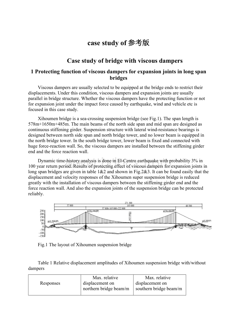
Xihoumenbridgeisasea-crossingsuspensionbridge(seeFig.1).Thespanlengthis578m+1650m+485m.Themainbeamsofthenorthsidespanandmidspanaredesignedascontinuousstiffeninggirder.Suspensionstructurewithlateralwind-resistancebearingsisdesignedbetweennorthsidespanandnorthbridgetower,andnolowerbeamisequippedinthenorthbridgetower.Inthesouthbridgetower,lowerbeamisfixedandconnectedwithhugeforce-reactionwall.So,theviscousdampersareinstalledbetweenthestiffeninggirderendandtheforcereactionwall.
Dynamictime-historyanalysisisdoneinEl-Centroearthquakewithprobability3%in100yearreturnperiod.Resultsofprotectingeffectofviscousdampersforexpansionjointsinlongspanbridgesaregivenintable1&2andshowninFig.2&3.ItcanbefoundeasilythatthedisplacementandvelocityresponsesoftheXihoumensupersuspensionbridgeisreducedgreatlywiththeinstallationofviscousdampersbetweenthestiffeninggirderendandtheforcereactionwall.Andalsotheexpansionjointsofthesuspensionbridgecanbeprotectedreliably.
Fig.1ThelayoutofXihoumensuspensionbridge
Table1RelativedisplacementamplitudesofXihoumensuspensionbridgewith/withoutdampers
Responses
Max.relativedisplacementonnorthernbridgebeam/m
Max.relativedisplacementonsouthernbridgebeam/m
Withoutdamper
Withdamper
Withoutdamper
Withdamper
Earthquake
Sitewave
0.3454
0.1397
0.3413
0.1354
El-Centro
0.3535
0.1901
0.3498
0.1850
Table2RelativevelocityamplitudesofXihoumensuspensionbridgewith/withoutdampers
Responses
Max.relativevelocityonnorthernbridgebeam/(m/s)
Max.relativevelocityonsouthernbridgebeam/(m/s)
Withoutdamper
Withdamper
Withoutdamper
Withdamper
Earthquake
Sitewave
0.2635
0.1381
0.2739
0.1941
El-Centro
0.5265
0.4535
0.5752
0.4783
Fig.2Comparisonofrelativedisplacementsofnorthbeamend
Fig.3Comparisonofrelativevelocitiesofnorthbeamend
2Casestudyonlateralresponsereductionoflong-spanrailwaycable-stayedbridgewithviscousdampers
Thelong-spanrailwaycable-stayedbridgeisasemi-floatingsystemwithspanlengthof81m+135m+432m+135m+81m(seeFig.4).Themainbridgebeamisasteeltrusswithwidthof18mandheightof14m.Thelengthofeachtrusssectionis13.5m.High-strengthsteelwiresareadoptedanddesignedasmaterialsofthe56pairsofstablecables.Thecablespacingdistanceis2.5m-4.0monthemainbridgetowerand13.5monthemainbridgebeam.Thebridgesurfaceisintegralorthotropicsteelplates.
DynamicresponsesareconductedbyMidassoftwareinthreeearthquakeswithprobability2-3%in50yearreturnperiod.Thepeakaccelerationsofthetheeearthquakesareallthesameof0.21g.ThespecificinstallationplacesoftheviscousdamperareshowninFig.5.ComputationalresultsofdynamictransverserelativedisplacementresponsesbetweenbridgepierandbeamareshowninFig.6andthehysteresiscurvesofviscousdampersbetweendampingforceanddisplacementareshowninFig.7.
Itcanbefoundthattheearthquake-reductionsystemisbetterthanothersystemsbysettingupviscousdampersbetweenauxiliarypier,transitionpierandbridgebeam,forlateralseismicresponseofmaintower,auxiliarypierandtransitionpiercanbesignificantlyreduced.Futuremore,seismicperformanceofpilefoundationsforauxiliaryandtransitionpiercanbeimproved.
Fig.4Thelong-spanrailwaycable-stayedbridgemodel(1#istransitionbridgepier,2#isauxiliarybridgepier,3#isbridgemaintower,4#isbridgemaintower,5#istransitionbridgepier,and6#isbridgeabutment)
Fig.5Installationplacesofviscousdampers
Fig.6Transverserelativedisplacementbetween1#pierandbridgebeam
Fig.7Hysteresiscurvesofviscousdamperat2#bridgepier.
3Casestudyonseismicperformanceimprovementforsouthernbranchmainbridgeofasea-crossingbridgewithviscousdampers
Thesouthernbranchmainbridgeofthesea-crossingbridgeinthiscasestudyisasemi-floatingsystemwithspanlengthof130m+290m+130m(seeFig.8).Thecross-sectionofthemainbeamofthesouthernbranchbridgeissingle-boxconcretesectionwiththreeholes.Theheightofthecrosssectionis3.5mandwidthis32.2m.Theheightofthemainbridgetoweris132.6mabovethebridgepile.
Thisbridgeliesintheearthquake-proneareasandthepeakaccelerationisverybiginthisarea.Inthiscasestudy,thepeakaccelerationis0.311g.Inordertoimprovethedynamicresponsesofthebridgeindesignearthquakeexcitations,viscousdampersareselectedandinstalledunderthemainbridgebeam,namelybetweenthemainlongitudinalbridgebeamandthebridgepier(seeFig.9).Parameteranalysisofviscousdampers,suchasdampingcoefficientsanddampingindex,isconductedsoastoobtaintheoptimaldamperparameters.TheparametersstudiedinthiscasestudyarelistedinTable3.
Theinfluenceofdamperparameters,dampingcoefficientsanddampingindex,totheenergydissipationratiosofthebridgeareshowninFig.10&11,respectively.AccordingtotheparameteranalysisbasedonthefiguresofFig.10&11,theoptimaldampingparameterscanthenbeeasilyobtainedandgiveninTable4.
Asaresult,twovibrationcontrolplansaredesigned.Thefirstoneisthat4viscousdampersareinstalledbetweenthemainbridgebeamandthebridgepierofthemaintower.Andthesecondisthat4viscousdampersareinstalledbetweenthemainbridgebeamandthebridgepierofthemaintower,and4dampersareinstalledbetweenthemainbridgebeamandthetransitionbridgepier.However,thetotaldampingcoefficientsofthetwoplansarethesameforcomparisonpurpose.ComparisonofenergydissipationratioofthebridgewiththetwocontrolplansareshowninFig.12.ThesymbolmeaningslistedintheFig.12aregiveninTable5.Obviously,theanalysisindicatesthatbothrelativedisplacementofkeypointsandseismicresponseofkeycomponentscouldbeobviouslyreducedwithreasonablychoosingtheparametersandlocationsofdampers.
Fg.8Thesouthernbranchmainbridgemodel
Fg.9Installationoftheviscousdamperunderthemainbridgebeam
Table3Parametersoftheviscousdampers
Items
Parametervalues
Dampingcoefficient(kN/(m/s)α)
1000
2000
3000
4000
6000
8000
10000
Dampingindex
0.2/0.3/0.5/1.0
(a)InfluenceofCtodisplacementofbeamend(b)InfluenceofCtodisplacementoftoptower
(c)InfluenceofCtomomentoftowerbottom(d)InfluenceofCtomomentoftoppile
Fig.10InfluenceofdampingcoefficientsCtotheenergydissipationratioofdifferentparameterresponses
(a)Influenceofαtodisplacementofbeamend(b)Influenceofαtodisplacementoftoptower
(c)Influenceofαtomomentoftowerbottom(d)Influenceofαtomomentoftoppile
Fig.11Influenceofdampingindexαtotheenergydissipationratioofdifferentparameterresponses
Table4Theoptimaldampingparametersoftheviscousdamperusedinthesouthernbranchbridge
Parameters
Values
DampingcoefficientC(kN/(m/s)0.3)
6000
Dampingindexα
0.3
DampingforceF(kN)
6000
Max.StrokeD(mm)
±400
Fig.12Comparisonofenergydissipationratioofthebridgewiththetwocontrolplans
Table5SymbolmeaningslistedintheFig.12.
Symbols
Meanings
Db
Max.relativedisplacementbetweenbeamendandtransitionpier
Dt
Max.relativedisplacementbetweentoptowerandbottomtower
Mt
Max.momentinthebottomtower
Mtp
Max.momentinthetopofthetowerpile
Mp
Max.momentinthebottomofthetransitionpier
Mpp
Max.momentinthetopofthetransition-pierpile
4CasestudyonperformanceimprovementofstaycableofJianshaobridgeusingviscousdampers
Inthiscasestudy,Jianshaocable-stayedbridgewith69,500mlengthand6maintowerisintroduced(seeFig.13).Thespanlengthis70m+200m+5×428m+200m+70m.Thecablesaremadeupofparallelhigh-strengthsteelwireswithdiametersizeof7mm.Totally,thereare576staycablesand432ofthesestaycablesareinstalledviscoussoastoimprovethevibrationperformance,seeFig.14.TheparametersoftheviscousdampersaregiveninTable6.
SitemeasurementvaluesofthelogarithmicdecrementratiooftheNo.Z5W-B10cablewithandwithoutviscousdampersaregiveninTable7.ThefreedecaycurvesoftheNo.Z5W-B10cableusingalsothesitemeasurementmethodareshowninFig.15.AndthehysteresiscurvesoftheviscousdampersareshowninFig.16.Theresultsshowthatviscousdamperscanbeabletocurbthevibrationofstaycables,whichcanbethepermanentvibrationcontrolmeasureforstaycables.Andtheresultsofthetestingdemonstratethattheviscousdampersshowstableperformance,alltheperformanceindexcanmeetthedesignrequirements.Themeasuredlogarithmicdecrementisabove6%,basicallyincompliancewiththechangingruleofthetheoreticalvalues,provingthattheviscousdampershavesoundvibrationdampingeffect.
Fig.13Jianshaocable-stayedbridge
(a)Beforeinstallationofviscousdampers(b)Afterinstallationofviscousdampers
Fig.14Siteinstallationofviscousdampers
Table6Parameters


- 配套讲稿:
如PPT文件的首页显示word图标,表示该PPT已包含配套word讲稿。双击word图标可打开word文档。
- 特殊限制:
部分文档作品中含有的国旗、国徽等图片,仅作为作品整体效果示例展示,禁止商用。设计者仅对作品中独创性部分享有著作权。
- 关 键 词:
- case study of参考版 of 参考
 冰豆网所有资源均是用户自行上传分享,仅供网友学习交流,未经上传用户书面授权,请勿作他用。
 铝散热器项目年度预算报告.docx
-
牛津上海版通用小学英语三年级上册Unit 12同步练习2II 卷.docx
-
论我国私营企业员工激励机制.docx
-
人教版五年级品德与社会上册全册教案.docx
-
开学啦国旗下讲话稿三分钟.docx
-
露天采矿学复习题.docx
-
六年级英语教师年度考核个人总结.docx
-
某路站综合体项PC吊装施工方案.docx
-
人教版九年级历史上册期末考试试题一套.docx
-
隆昌妇幼保健院.docx
-
芦二矿抽采达标中长期规划.docx
-
看拼音写词语.docx
-
模拟磁盘调度算法系统的设计毕业设计.docx
-
每周一条名言警句或一首诗词.docx
-
棉花膜下滴灌示范工程设计总结报告.docx
-
九年级化学教案第十单元酸和碱教案新人教版.docx
-
宁波市水资源公报.docx
-
农业实用技术培训工作意见与农业局上半年工作总结范例两篇汇编.docx
-
平行线的判定.docx
-
内部会计管理制度11成本核算制度.docx
-
盘扣式脚手架支撑方案.docx
-
旅游规划模板.docx
-
煤矿大本大专毕业设计大采高综采工作面作业规程.docx
-
美学选择题整理课件资料.docx
-
名家论腹泻慢性肠炎.docx
-
宁夏银川市第一中学学年高一上学期期中考试地理试题解析解析版.docx
-
年产吨精密纤维纸项目建设建议书.docx
-
农技推广中心工作总结.docx
-
彭宇案的法逻辑批判.docx
-
宁夏仕奇房产网发布份房地产交易情况.docx
-
项目推荐书智能温控节能系统.docx
-
区县节日期间加强消防安全讲话稿与区发改委领导班子述职述廉报告汇编.docx
-
拆除工程施工组织设计.docx
-
在开学典礼上的讲话.docx
-
英语课标知识大赛参考题库.docx
-
幼儿告状行为的研究及指导策略.docx
-
制作艾绒方法.docx
-
千字文带注音.docx
-
资产的单项选择题doc 24页.docx
-
版高考生物人教版 单元过关检测七.docx
-
学习师德标兵心得体会5篇.docx
-
都市丽人创业计划书0.docx
-
广东省届高三百所学校质量分析联合考试英语试题.docx
-
校园网络总体设计方案终版.docx
-
巡检工讲义.docx
-
小学生安全教育记录表1.docx
-
小学语文四年级.docx
-
战略成本管理几个基本概念.docx
-
通用考博英语写作.docx
-
学年人教版生物选修一讲义专题4 课题2 探讨加酶洗衣粉的洗涤效果.docx
-
学生会演讲稿精选8篇全面版.docx
